High Voltage Schering Bridge

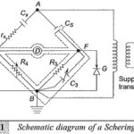
High Voltage Schering Bridge: In the power frequency range (25 to 100 Hz) High Voltage Schering Bridge is a very versatile and sensitive bridge and is readily suitable for high…

Continue Reading High Voltage Schering Bridge
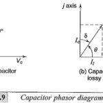
Dielectric Constant and Loss

Dielectric Constant and Loss: Many insulating substances have dielectric constant greater than unity and have Dielectric Constant and Loss when subjected to a.c. voltages. These two quantities, namely, the dielectric…

Continue Reading Dielectric Constant and Loss

Direct Current Resistivity Method

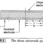
Direct Current Resistivity Method: The specimen shape and the electrode arrangement should be such that the Direct Current Resistivity Method can be easily calculated. For a solid specimen, the preferable…

Continue Reading Direct Current Resistivity Method

Insulation Coordination of Substation

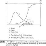
Insulation Coordination of Substation: For steep fronted lightning waves at Insulation Coordination of Substation and at different points on lines, the voltages at sub-stations may exceed the protective level depending…

Continue Reading Insulation Coordination of Substation

Transmission Line Overvoltage Protection

Transmission Line Overvoltage Protection: Transmission Line Overvoltage Protection against natural or lightning overvoltages and minimizing the lightning overvoltages are done by suitable line designs, providing guard and ground wires, and…

Continue Reading Transmission Line Overvoltage Protection

Distortion of Travelling Waves

Attenuation and  Distortion of Travelling Waves: As a Travelling Waves moves along a line, it suffers both attenuation and distortion. The decrease in the magnitude of the wave as it…

Continue Reading Distortion of Travelling Waves

Rogowski Coil Integrator Design

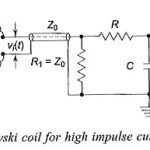
Rogowski Coil Integrator Design: If a Rogowski Coil Integrator Design is placed surrounding a current carrying conductor, the voltage signal induced in the coil is vi(t) = M dI(t)/dt where…

Continue Reading Rogowski Coil Integrator Design

Cascade Transformer Connection

Cascade Transformer Connection: Figure 6.10 shows the Cascade Transformer Connection units in which the first transformer is at the ground potential along with its tank. The second transformer is kept…

Continue Reading Cascade Transformer Connection