Dielectric Constant and Loss:
Many insulating substances have dielectric constant greater than unity and have Dielectric Constant and Loss when subjected to a.c. voltages. These two quantities, namely, the dielectric constant and the loss depend on the magnitude of the voltage stress and on the frequency of the applied voltage. When a dielectric is used in an electrical equipment such as cable or a capacitor, the variation of these quantities with frequency is of importance. The microscopic properties of the dielectric are described by combining the variation of the above two quantities into one “complex quantity” known as “complex permittivity” and determining them at various frequencies.
A capacitor connected to a sinusoidal voltage source v = v0 exp (jωt) with an angular frequency ω = 2πf stores a charge Q = C0v and draws a charging current Ic = dQ/dt = jωC0v. When the dielectric is vacuum, C0 is the vacuum capacitance or geometric capacitance of the capacitor
If the capacitor is filled with a dielectric of permittivity ε′, the capacitance of the capacitor is increased to C = C0ε′/ε0 = C0K′ where K′ is the relative Dielectric Constant and Loss of the material with respect to vacuum.
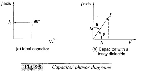
Under these conditions, if the same voltage V is applied, there will be a charging current Ic and loss component of the current, I1. I1 will be equal to GV where G represents the conductance of the dielectric material. The total current I = Ic + I1 = (jωC + G)V.. The current leads the voltage by an angle θ which is less than 90°. The loss angle δ is equal to (90 – θ)°. The phasor diagrams of an ideal capacitor and a capacitor with a lossy dielectric are shown in Figs 9.9a and b.
It would be premature to conclude that the Dielectric Constant and Loss material corresponds to an R-C parallel circuit in electrical behaviour. The frequency response of this circuit which can be expressed as the ratio of the loss current to the charging current, i.e. the loss tangent
![]()
may not at all agree with the result actually observed, because the conductance need not be due to the migration of charges or charge carriers but may represent any other energy consuming process. Hence, it is customary to refer the existence of a loss current in addition to the charging current by introducing “complex permittivity“
![]()
so that current I may be written as
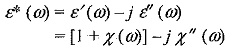
K* is called the complex relative permittivity or complex dielectric constant, ε′ and K’ are called the permittivity, and relative permittivity and ε′′ and K” are called the loss factor and relative loss factor respectively.
The loss tangent![]()
The product of the angular frequency and ε′′ is equivalent to the dielectric conductivity σ
![]()
The dielectric conductivity sums up all the dissipative effects and may represent the actual conductivity as well as the energy loss associated with the frequency dependence (dispersion) of e’, i.e. the orientation of dipoles in a dielectric.
In dielectric measurements, often, the geometrical capacitance and the capacitance of the system with a dielectric material are obtained. The ratio of the above two measurements gives the relative permittivity ε′/ε0 = K′. This is sometimes referred to as the dielectric constant or εr.
Dielectric Response in Time Varying (a.c.) Fields:
In dielectric materials, the polarization P, the electric field E and the flux density D are related by the equation
![]()
where, X is the dielectric susceptibility of the material with a varying electric fields E(t), the polarization P induces current in a Dielectric Constant and Loss due to charge migration whenever an electric field is suddenly applied. With DC, if the material has a conductivity σ, then the current density obtained is σ E(t) and the polarization displacement current will be δ D(t)/δt. Hence the total current density produced is
where, δ(t) is instantaneous impulse response and f(t) is the further response obtained.
Hence, the polarization current obtained in terms of the geometrical capacitance C0 (without material) is,
where, V is the applied voltage that produces the electric field E(t)
If the equations are transformed into frequency domain (ω) and with the complex frequency concept, we get
![]()
where F(ω) is the complex susceptibility.
Hence, the complex permittivity ε* (ω) may be written as
From this, the dissipation factor tan δ is obtained as
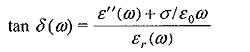
where εr(ω) is the effective dielectric constant ε (ω)/ε0.
The above equations clearly show that the loss factor tan δ is a function of ω and hence is to be determined or measured over a frequency range.
Measurement Ranges:
Lumped circuits are used in the measurements of the Dielectric Constant and Loss and tan oi over the frequency range from d.c. (0 Hz) to about 100 MHz Neither of these quantities are determined directly. Measurements of capacitance using either a null method or a deflection method is employed over the low frequency range (0-10 Hz), where bridge methods are difficult. Normally, the shape of the current-time characteristic curve is determined from which these parameters are deduced. Sometimes, modified bridge methods are extended to this frequency range also. Over the medium frequency range (10 Hz to 106 Hz), bridge methods are employed. The commonly employed bridge networks are the four arm Schering bridge to operate from power frequency (50 Hz) to about 100 kHz and the “High Voltage Schering Bridge” for power frequency (50 Hz) when the effect of voltage stress on Dielectric Constant and Loss and tan δ is required. Over the high frequency range (100 kHz to 100 MHz), bridge circuits present problems in shielding and the errors of measurements become excessive. Micrometer electrodes using vernier capacitors (electrode separation being controlled and measured to micrometer (μm) accuracy have to be employed to avoid errors due to residual impedances. Using these methods, dissipation factor, tan δ, is usually obtained from the width of the resonant curve by varying either the frequency or the susceptibility of the circuit. At frequencies above 100 MHz, the lumped circuit approximation is not valid as the wavelength of the frequency approaches that of the specimen thickness. Microwave techniques like “the travelling wave” or “the standing wave” measurements are to be employed beyond the frequency limit of 108 Hz. The information obtained from the measurements of tan δ and the complex permittivity help in assessing the quality of the dielectric and the insulation system.
- Variation and sudden change in tan δ value with applied voltage is an indication of the inception of partial discharge (P.D.). This is used to determine the inception level of internal discharges and losses due to P.D. in high voltage equipment.
- To study the variation of the Dielectric Constant and Loss properties with frequency. Much of the interest in this study is concerned with the frequency region where dispersion occurs, i.e. where the permittivity reduces with rise in the frequency.