What is Focusing Device in Cathode Ray Oscilloscope and why it is required?
Because of the mutual repulsion between the electrons, the convergent beam coming out from the accelerating anode has a tendency to spread from the axis. To avoid this and to bring the beam to a sharp focus at the screen, some Focusing Device in Cathode Ray Oscilloscope is required. The Focusing Device in Cathode Ray Oscilloscope may be either electrostatic or magnetic. Electrostatic focusing is used in a CRO whereas magnetic focusing is used in a TV picture tube.
Electrostatic Focusing:
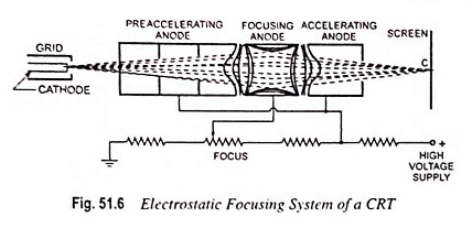
An electrostatic focusing system is shown in Fig. 51.6. Electrostatic lens consists of three anodes, with the middle anode at a lower potential than the other two electrodes.
In Fig. 51.7 two anodes and its electrostatic lines and equipotential surfaces are shown. A pd is kept between these two electrodes so that an electric field is generated between them. Spreading of electric field is caused because of repulsion between electric lines. If equipotential lines are drawn, as shown in Fig. 51.7, they would bulge at the centre of the two anodes.
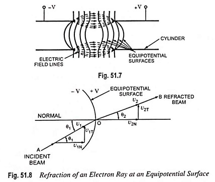
As we know that electrons move in a direction opposite to that of electric field lines and equipotential surfaces are perpendicular to the electric field lines so force on the electron is exerted in the direction normal to the equipotential surface.
Electrons entering at the centre line of the two anodes experience no force but electrons displaced from the centre line experience a force normal to the direction of equipotential surface and deflects, as shown in Fig. 51.8. In Fig. 51.8 an equipotential surface is shown, in which an electron with velocity v1 and at an angle θ1 to the normal of equipotential surface enters and experiences a force in a direction normal to the equipotential surface. Thus the velocity of the electron increases to v2. This force on the electron is exerted in the direction normal to equipotential surface so only the normal component of electron velocity v1N increases to v2N and the tangential component of velocity v1T remains the same.
From Fig. 51.8
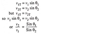
From the above expression it is obvious that equipotential surface acts as a concave lens in geometrical optics. That is why, this focusing system is named as an electrostatic lens.
Now if we go back and refer to Fig. 51.6, it can be seen that because of middle anode at a lower potential, electron beam coming from the cathode and passing through the first concave electrostatic lens tends to become more aligned with the axis of CRT and when it enters at the second concave electrostatic lens, formed between two anodes at different potentials, it is focused at the phosphor screen. Focal length of the electrostatic lens can be adjusted by varying potential of middle anode with respect to other two anodes. Thus the electron beam can be made to focus at the screen very precisely.
Electrostatic Deflection of Moving Electrons in CRO Tubes: We know that a force is experienced by an electron when it is kept in a uniform electric field. This principle is the basis for the deflection of electron beam owing to deflection plates.
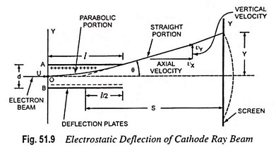
Let us consider an electron having initial velocity of u m/s along X-axis at point O in the space between the plates A and B, each of length l metres and separated by a distance of d metres. Let the pd across the plates be of V volts. For simplicity, let us assume that the field is uniform and does not extend beyond the ends of the plates.
Axial velocity of electron remains unchanged and is equal to u as there is no axial force and, therefore, no axial acceleration.
The period during which an electron remains in the region between the two plates is given by the expression.
![]()
There is no initial velocity along Y-axis but has an acceleration along Y-axis given by the expression.
![]()
The velocity of electron along Y-axis after time t is given by the expression.
![]()
After the electron leaves the region between the deflection plates, it travels in a straight line, because there is no field acting on it. A simple extension of this development will show that if this line is extended backward, it intercepts the X-axis at the centre of the plates i.e. at x = l/2 (approximately). Let S be distance along the X-axis from this point to the screen. Then the deflection y can be determined by similar triangles. Thus
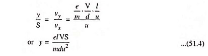
If Va is the accelerating voltage and Vd is the deflecting voltage, then,

![]()
Substituting u2= 2eVa/m in Eq. (51.4) we get

From the above expression we can conclude that for a fixed accelerating voltage Va and dimensions of CRT, the deflection of electron beam on the screen is directly proportional to the deflection voltage Vd. So CRT can be employed as a linear voltage indicating device. Image on the screen of CRT follows the variation of deflection voltage Vd in a linear fashion.
The deflection sensitivity of a cathode ray tube, which is defined as the vertical deflection of the beam on the screen per unit deflecting voltage, is given by the expression
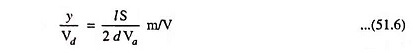
The deflection factor, the reciprocal of deflection sensitivity, is given by the expression

Length of the trace obtained on the screen
![]()
From the above expressions for deflection sensitivity and deflection factor it can be said that deflection factor for a CRT varies linearly with the accelerating voltage. A high accelerated electron beam possesses more kinetic energy and so produces a brighter image on the screen of the CRT but a high deflection voltage is required for deflecting the beam.
Typical values of deflection sensitivity are 0.1 mm/volt to 1.00 mm/volt.
Electromagnetic Focusing:
The electromagnetic method of Focusing Device in Cathode Ray Oscilloscope is based on the fact that an electron which enters a constant magnetic field perpendicular to its path is deflected and moves in a circular path. The magnetic field produced is parallel to the axis of the tube. The electrons moving parallel to the axis are not affected by the magnetic field, while electrons having a component of velocity away from the axis move in a spiral path which finally brings them back to the axis.
The axis of the electromagnetic coil coincides with the electron beam axis. The coil may extend the complete tube length or it may be concentrated in a smaller region. First type of coil is used in “image orthicon” camera tube in television, whereas the second type of coil is employed in picture tube of TV receiver, in radar indicator and in general purpose CRO.
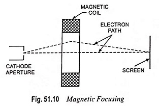
The principle of magnetic focusing is illustrated in Fig. 51.10. The electromagnetic coil surrounds the tube such that the lines of magnetic field are uniformly distributed and are parallel to the axis of tube. As mentioned above, the electrons moving parallel to the tube axis are not affected by the magnetic field, while the electrons moving at an angle to the axis experience a force. The direction of this force is perpendicular both to the direction of motion of the electron and to the magnetic field. Thus, two forces act on the electron, one the attractive force of the anode causing it to move forward and another due to magnetic field causing the side motion. Thus the electron moves in a spiral path which finally returns to the axis of the tube.
Electromagnetic Deflection of Cathode Ray Beam: Let us consider an electron having an initial velocity of u m/s along the tube axis OP at point O and assume that there is a uniform magnetic field of flux density B in Wb/m2 covering an axis distance l.
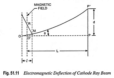
Then the force acting on the electron entering the field is eBu in a direction perpendicular to the path which is an arc of radius R given by R = mu/eB.
The electron emerges from the field and moves in a direction inclined at an angle θ to the axis and strikes the screen at P’. If the total angular deflection θ is very small, then
![]()
and angular deflection,
![]()
In most practical cases L is very much larger than l so that little error will be caused in assuming that the straight line MP’, if projected backward, will pass through the centre O’ of the region of the magnetic field. Then
![]()
Substituting θ = leB/mu from Eq. (51.9) in above equation we have
![]()
Substituting

from Eq. (51.5) in above equation we have
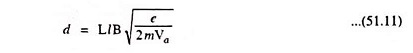
This equation is again approximate as it neglects the variations of field at the edges.
The magnetic deflection sensitivity Sm, defined as the deflection (in metre) on the screen caused by unit magnetic flux density, is given by
![]()
Alternatively, the sensitivity Sm is defined as the deflection, in mm, on the screen when 1 mA current flows through the deflection coil. This is expressed in mm/mA.