Emitter Coupled Clipper Circuit:
An emitter coupled clipper using two transistors is shown in Fig. 30.71. It is a two level clipper in which the input is applied to the base of one of the transistors and the base of the other transistor is kept at a fixed voltage.
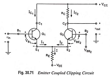
Consider initially that input voltage vin is negative enough to ensure that transistor Q1 is in cutoff. In this condition only transistor Q2 carries current. Let us also consider that VBB2 has been adjusted so that transistor Q2 is in its active region and current in the emitter resistance RE remains constant. This will be valid only if
![]()
As the input voltage rises, transistor Q1 will eventually come out of cutoff, both transistors will be carrying current, but current in transistor Q2 decreases while current in transistor Q1 increases, the sum of currents in the two transistors remaining unchanged and equal to emitter resistance current I. The input signal appears at the output, amplified but not inverted.
As input voltage vin continues its excursion in positive direction, the common emitter follows the base of transistor Q1. As the base of transistor Q2 is fixed, a point will be reached when the rising emitter voltage cuts off transistor Q2. In summary, the input signal is amplified but limited twice, once by the cutoff of transistor Q1 and once by the onset of cutoff in transistor Q2.
The total range Δvout over which the output can follow the input is IRE and is, therefore, adjustable through the adjustment of current I.
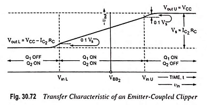
The absolute voltage of the portion of the input waveform selected for transmission may be selected through an adjustment of a biasing voltage on which vin is superimposed or through an adjustment of VBB2. The total range of input voltage Δvin between clipping limits is Δvout/A, where A is the gain of the amplifier stage. The transfer characteristic of an emitter coupled clipper is given in Fig. 30.72.