Series Voltage Regulator – Block Diagram and Working Principle:
The basic connection of a series voltage regulator circuit is shown in the block diagram given in Fig. 43.4.
The series element controls the magnitude of the input voltage that gets to the output. The output voltage is sampled by a circuit that provides a feedback voltage to be compared to a reference voltage.
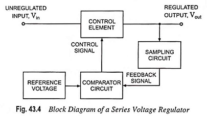
If the output voltage increases, the comparator circuit provides a control signal to cause the series control element to reduce the magnitude of the output voltage—thereby maintaining the output voltage.
On the other hand, if the output voltage falls, the comparator circuit provides a control signal to cause the series control element to increase the magnitude of output voltage. Thus, the output voltage is maintained constant.