Modern Laboratory Signal Generator Block Diagram and its Working:
Modern Laboratory Signal Generator – To improve the frequency stability, a single master oscillator is optimally designed for the highest frequency range and frequency dividers are switched in to produce lower ranges. In this manner the stability of the top range is imparted to all the lower ranges.
The master oscillator is made insensitive to temperature variations and also to the influence of the succeeding stages by careful circuit design. Temperature compensation devices are used for any temperature changes. The block diagram of the Modern Laboratory Signal Generator is given in Fig. 8.3.
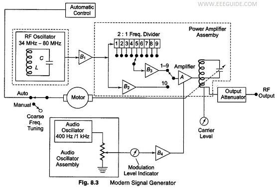
The highest frequency range of 34 – 80 MHz, is passed through B1, an untuned buffer amplifier. B2 and B3 are additional buffer amplifiers and A is the main amplifier. The lowest frequency range produced by the cascaded frequency divider (9 frequency dividers of 2:1 ratio are used), is the highest frequency range divided by 512, or 29, or 67 – 156 kHz. Thus, the frequency stability of the highest range is imparted to the lower frequency ranges.
The use of buffer amplifiers provides a very high degree of isolation between the master oscillator and the power amplifier, and almost eliminates all the frequency effects (distortion) between the input and output circuits, caused by loading.
Range switching effects are also eliminated, since the same oscillator is used on all bands. The master oscillator is tuned by a motor driven variable capacitor. For fast coarse tuning, a rocker switch is provided, which sends the indicator gliding along the slide rule scale of the main frequency dial at approximately 7% frequency changes per second. The oscillator can then be fine tuned by means of a large rotary switch (control), with each division corresponding to 0.01% of the main dial setting.
The master oscillator has both automatic and manual controllers. The availability of the motor driven frequency control is employed for programmable automatic frequency control devices.
Internal calibration is provided by the 1 MHz crystal oscillator. The small power consumption of the instruments makes it relatively easy to obtain excellent regulation and Q stability with very low ripple. The supply voltage of the master oscillator is regulated by a temperature compensated reference circuit.
The modulation is done at the power amplifier stage. For modulation, two internally generated signals are used, that is, 400 Hz and 1 kHz. The modulation level may be adjusted up to 95% by a control device. Flip-flops can be used as frequency dividers to get a ratio of 2:1.