Bias Stability Factor of Transistor:
Bias Stability Factor of Transistor – Only the fixing of a suitable operating point is not sufficient but it is also to be ensured that the operating point remains stable i.e., it does not shift due to change in temperature or due to variations in transistor parameters (due to replacement of transistor). Unfortunately it is not possible in practice unless special efforts are made to achieve it.
The maintenance of the operating point stable (independent of temperature variations or variations in transistor parameters) is known as stabilization.
1. Need For Bias Stabilization:
The stabilization of operating point is essential because of (i) temperature dependence of collector current IC (ii) individual variations and (iii) thermal runaway.
(i) Temperature Dependence of Collector Current IC: The instability of collector current IC, being equal to βIB + (1 + β)ICO, due to variations in temperature, is caused because of the following three main factors.
- Reverse saturation current (leakage current), ICO, which doubles for every 10°C rise in temperature.
- Transistor current gain, β, which increases with the increase in temperature.
- Base-emitter voltage, VBE, which decreases by 2.5 mV per °C.
Any or all of the above factors can cause the bias point to shift from the values originally fixed by the circuit because of a change in temperature.
Though with the change in temperature collector-emitter voltage VCE also changes but the change is very small and collector current lC is not affected.
(ii) Individual Variations: The values of β and VBE are not exactly the same for any two transistors even of the same type. For an example BC147 is a silicon transistor with β varying from 100 to 600 (for one transistor β may be 100 and for the other it may be 600). For an instance, it has not been possible to control the base width and it may vary, although slightly, from one transistor to another one of the same type. Such little variations result in a large change in the transistor parameters such as β, VBE etc.
Thus when a transistor is replaced by another transistor of the same type, the operating point may shift. Such problems do not arise in case of vacuum tube circuits because it is possible to manufacture vacuum tubes with identical characteristics.
(iii) Thermal Runaway: The collector current IC, being equal to β IB + (1 + β)ICO, increases with the increase in temperature. This leads to increased power dissipation with further increase in temperature. Being a cumulative process, it can lead to thermal runaway resulting in burn out of the transistor. The self destruction of an unstabilized transistor is called the thermal runaway.
However, if by some modification, IB is made to fall with increase in temperature automatically, then decrease in the term βIB can be made to neutralize the increase in the term (1 + β)ICO, thereby keeping lC almost constant. This will achieve thermal stability resulting in bias stability.
2. Means of Achieving Stability For Operating Point:
Operating point Stability Factor of Transistor may be achieved by adopting either stabilization techniques or compensation techniques.
Stabilization technique makes use of a resistive biasing circuit that permits such a variation of base current (biasing current) IB as to maintain collector current lC almost constant inspite of variations in reverse saturation current ICO, base-emitter voltage VBE and β.
Compensation techniques make use of temperature sensitive devices such as diodes, transistors, thermistors etc. Such devices produce compensating voltages and currents so as to make operating point stable.
Additional means are adopted to maintain the ambient and junction temperatures constant. Air-conditioning or thermostat chambers (wherever possible) may be used for maintaining the ambient or case temperature constant. Heat sink and air blast may be used to remove heat from the transistor.
Stability Factor of Transistor:
The degree of success achieved in stabilizing lC in the face of variations in ICO is expressed in terms of Stability Factor of Transistor S and it is defined as the rate of change of collector current w.r.t. ICO keeping β and VBE constant

From above equation it is obvious that smaller is the value of S, higher is the stability. The ideal value of S is unity (because lC includes ICO) but it is never possible to achieve it in practice.
While defining stability factor S above, VBE and β are assumed to remain constant while they vary with temperature. Hence other two Stability Factor of Transistor SV and Sβ are defined as below :
Stability factor SV is defined as the rate of change of collector current IC with base-emitter voltage VBE, keeping ICO and β constant
![]()
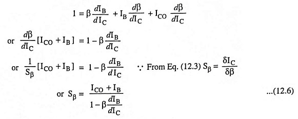
Stability factor Sβ is defined as the rate of change of collector current IC with respect to β keeping ICO and VBE constant i.e.,

1. General Expression For Stability Factor S:
In the active region the basic relationship between collector current IC and base current IB is given below:
![]()
Differentiating above Eq. (12.4) with respect to IC considering β to be constant, we have
![]()
So Stability Factor of Transistor,
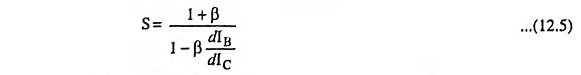
The value of dIB/dIC depends upon the biasing arrangement used and for determination of the stability factor S, it is only necessary to find the relationship between lC and IB.
2. General Expression For Stability Factor Sβ:
Differentiating Eq. (12.4) w.r.t. IC considering ICO to be constant we have