Sensitivity Factor in Power System:
A security analysis program is run in a load dispatch centre very quickly to help the operators. This can be attempted by carrying out an approximate analysis and using a computer system having multiple processors or vector processors for speedy analysis. The system may be adequately described and an equivalent should be used for neighbors connected through tie-lines. We can eliminate all non-violation cases and run complete exact program for “critical” cases only. This can be achieved by using techniques such as “contingency selection” or “contingency screening”, or “contingency ranking”. Thus it will be easy to warn the operation staff in advance to enable them to take corrective action if one or more outages will result in serious overloads or any violations. One of the simplest ways to present a quick calculation of possible overloads is to employ network (linear) Sensitivity Factor in Power System. These Sensitivity Factor in Power System give the approximate change in line flows for changes in generation in the system and can be calculated from the DC load flow.
They are mainly of two types:
- Generation shift factors
- Line outage distribution factors
Briefly we shall now describe the use of those factors without deriving them.
The generation shift factors, αli are defined as:
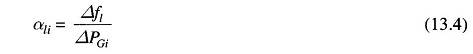
where
- Δfl = Change in MW power flow on line l when a change in generation, ΔPGi takes place at the ith bus
Here, it is assumed that ΔPGi is fully compensated by an equal and opposite change in generation at the slack (reference) bus, with all other generators remaining fixed at their original power generations. The factor αli then gives the Sensitivity Factor in Power System of the lth line flow to a change in generation at ith bus. Let us now study the outage of a large generating unit and assume that all the lost generation (P0Gi) would be supplied by the slack bus generation. Then
![]()
and the new power flow on each line could be calculated using a precalculated set of “α” factors as given below.
![]()
where
- f̂l = power flow on lth line after the failure of ith generator
- f∘l = power flow on lth line before the failure or pre contingency power flow
The values of line flows obtained from Eq. (13.6) can be compared to their limits and those violating their limit can be informed to the operator for necessary control action.
The generation shift Sensitivity Factor in Power System are linear estimates of the change in line flow with a change in power at a bus. Thus, the effects of simultaneous changes on a given number of generating buses can be computed using the principle of superposition.
Let us assume that the loss of the ith generator is to be made up by governor action on all generators of the interconnected system and pick up in proportion to their maximum MW ratings. Thus, the proportion of generation pick up from unit k (k ≠ i) would be
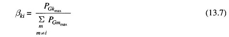
where
- PGMmax = maximum MW rating for mth generator
- βki = proportionality factor for pick up on kth unit when ith unit fails.
Now, for checking the lth line flow, we may write
![]()
In Eq. (13.8) it is assumed that no unit will violate its maximum limit. For unit limit violation, algorithm can easily be modified.
Similarly the line outage distribution factors can be used for checking if the line overloads when some of the lines are lost.
The line outage distribution factor is defined as:
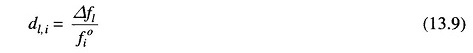
where
- dl,i = line outage distribution factor when monitoring lth line after an outage of ith line.
- Δfl = change in MW flow on lth line.
- f∘i = precontingency line flow on ith line
If precontingency line flows on lines l and i, the power flow on line l with line i out can be found out employing “d” factors.
![]()
where
- f∘l and f∘i = precontingency or preoutage flows on lines l and i respectively
- f̂l = power flow on lth line with ith line out.
Thus one can check quickly by precalculating ‘d’ factors all the lines for overloading for the outage of a particular line. This can be repeated for the outage of each line one by one and overloads can be found out for corrective action.
It may be noted that a line flow can be positive or negative. Hence we must check f against –fl max as well as fl max,. Line flows can be found out using telemetry systems or with state estimation techniques. If the network undergoes any significant structural change, the Sensitivity Factor in Power System must be updated.