Crystal Oscillators – Circuit, Working, Advantages and Disadvantages:
In crystal oscillators, the usual electrical resonant circuit is replaced by a mechanically vibrating crystal. The crystal (usually quartz) has a high degree of stability in holding constant at whatever frequency the crystal is originally cut to operate. The crystal oscillators are, therefore, used whenever great stability is needed, for example, in communication transmitters, and receivers, digital clocks etc.
A quartz crystal exhibits a very important property known as piezoelectric effect. When a mechanical pressure is applied across the faces of the crystal, a voltage proportional to the applied mechanical pressure appears across the crystal. Conversely, when a voltage is applied across the crystal surfaces, the crystal is distorted by an amount proportional to the applied voltage. An alternating voltage applied to a crystal causes it to vibrate at its natural frequency.
Besides quartz, the other substances that exhibit the piezoelectric effect are Rochelle salt and tourmaline. Rochelle salt exhibits the greatest piezoelectric effect, but its applications are limited to manufacture of microphones, headsets and loudspeakers. It is because the Rochelle salt is mechanically the weakest and strongly affected by moisture and heat. Tourmaline is most rugged but shows the least piezoelectric effect. Quartz is a compromise between the piezoelectric effect of Rochelle salt and the mechanical strength of tourmaline. It is inexpensive and readily available in nature. It is mainly the quartz crystal that is used in radio frequency (RF) oscillators.
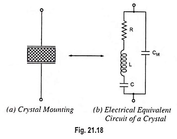
For use in electronic oscillators, the crystal is suitably cut and then mounted between two metal plates, as shown in Fig. 21.18 (a). Although the crystal has electromechanical resonance but the crystal action can be represented by an electrical resonant circuit, as shown in Fig. 21.18 (b). The crystal actually behaves as a series R-L-C circuit in parallel with CM where CM is the capacitance of the mounting electrodes. Because the crystal losses, represented by R, are small, the equivalent crystal Q is high—typically 20,000. Values of Q up to 106 can be obtained by making use of crystals.
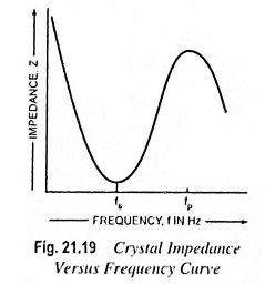
Because of presence of CM, the crystal has two resonant frequencies. One of these is the series resonant frequency fs at which 2πfL = 1/2πfC and in this case the crystal impedance is very low. The other is parallel resonance frequency fp which is due to parallel resonance of capacitance CM and the reactance of the series circuit. In this case crystal impedance is very high. The impedance versus frequency curve of the crystal is shown in Fig. 21.19. In order to use the crystal properly it must be connected in a circuit so that its low impedance in the series resonant operating mode or high impedance in the antiresonant or parallel resonant operating mode is selected.
Two resonant frequencies are given by the equations
Series resonant frequency,
![]()
Parallel resonant frequency,
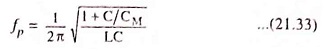
It appears that fp is higher than fs but the two frequencies are very close to each other. It is due to the fact that the ratio C/CM is very small.
To stabilize the frequency of an oscillator, a crystal may be operated at either its series or parallel resonant frequency.
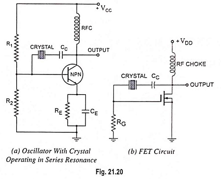
To excite a crystal for operation in the series resonant mode it may be connected as a series element in a feedback path, as shown in Fig. 21.20(a). In this mode of operation the crystal impedance is the smallest and the amount of positive feedback is the largest. Resistors R1, R2 and RE provide a voltage-divider stabilized dc bias circuit, the capacitor CE provides ac bypass of the emitter resistor RE and the radio frequency coil (RFC) provides for dc bias while decoupling any ac signal on the power lines from affecting the output signal.
The voltage feedback signal from the collector to the base is maximum when the crystal impedance is minimum (i.e. in series resonant mode). The coupling capacitor CC has negligible impedance at the circuit operating frequency but blocks any dc between collector and base. The circuit shown in Fig. 21.20(a) is generally called the Pierce crystal. The resulting circuit frequency of oscillations is set by the series resonant frequency of the crystal. Variations in supply voltage, transistor parameters, etc. have no effect on the circuit operating frequency which is held stabilized by the crystal. The circuit frequency stability is set by the crystal frequency stability, which is good.
FET circuit with crystal operating in series resonance is shown in Fig. 21.20(b).
Use of FET is desirable because its high input impedance results in light loading of the crystal which (i) results in good stability and (ii) does not lower the Q value.
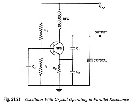
Oscillator circuit with crystal operating in parallel resonance (a modified Colpitt’s oscillator circuit) is illustrated in Fig. 21.21. Since the parallel resonant impedance of a crystal is of a maximum value, it is connected in parallel. C1 and C2 form a capacitive voltage divider which returns a portion of the output voltage to the transistor emitter. Transistor NPN combined with R1, R2, RFC and RE, constitutes a common base circuit. Capacitor C3 provides an ac short circuit across R2 to ensure that the transistor base remains at a fixed voltage level. As the output voltage increases positively, the emitter voltage also increases, and since the base voltage is fixed, the base-emitter voltage is reduced. The reduction in VBE causes collector current IC to diminish, and this in turn causes the collector voltage VC to increase positively. Thus, the circuit is applying its own input, and a state of oscillation exists. The crystal in parallel with C1 and C2 permits maximum voltage feedback from the collector to emitter when its impedance is maximum, i.e., at its parallel resonant frequency. At other frequencies, the crystal impedance is low, and so the resultant feedback voltage is too small to sustain oscillations. The oscillation frequency is stabilized at the parallel resonant frequency of the crystal
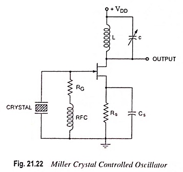
A Miller crystal controlled oscillator circuit is shown in Fig. 21.22. A tuned L-C circuit in the drain section is adjusted near the crystal parallel resonant frequency. The maximum gate-source signal occurs at the crystal antiresonant frequency, controlling the circuit operating frequency.
Advantages:
- It is very simple circuit as it does not need any tank circuit other than crystal itself.
- Different oscillation frequencies can be had by simply replacing one crystal with another.
- The Q factor, which is a measure of the quality of resonance circuit of a crystal, is very high. The Q factor of a crystal may range from 104 to 106 whereas the L-C circuit may have a Q factor only of the order of 100.
- Most crystals will maintain frequency drift to within a few cycles at 25°C. For greater frequency stability, the crystal is often contained in an insulated enclosure termed as crystal oven in which the temperature is thermostatically controlled. In this way it is possible to have frequency drifts less than 1 part in 1010.
Disadvantages:
- The crystal oscillators have a very limited tuning range (or not at all). They are used for frequencies exceeding 100 kHz.
- The crystal oscillators are fragile and, therefore, can only be used in low power circuits.
Crystal oscillators must be designed to provide a load capacitance on the crystal as per specifications listed by the manufacturer. This requirement is essential for obtaining oscillations at the specified frequency. It is also important from the point of view of limiting the power supplied to the crystal to the specified maximum. Too much crystal power causes distortion in the oscillator waveform. It also causes overheating of the crystal, consequently rendering the resonant frequency unstable. More important is that the thin plated electrodes may be melted off an overdriven crystal, destroying the device. Typical maximum drive levels for plated crystals vary from 2 mW to 10 mW.
The maximum permissible drive power limits the ac voltages that may be applied across the crystal and consequently affects the design of oscillator circuits. Crystal manufacturers usually specify the resistance of individual crystal, as well as maximum drive power. From these two, the maximum crystal ac voltage may be determined by using the relation P = V2/R.