Negative Resistance Oscillators – Working and Types:
Negative resistance oscillators make use of negative resistance elements such as tetrodes, tunnel diodes, unijunction transistors etc. There are two types of negative resistance oscillators, which are commonly used for high frequency generation. These are dynatron and tunnel diode oscillators.
Dynatron operates in the negative resistance region of the characteristics of a tetrode, which is coupled to an L-C tank circuit.
Tunnel diode oscillator makes use of a tunnel diode for producing oscillations.
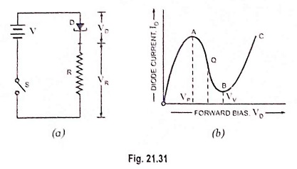
Now consider a circuit shown in Fig. 21.31 (a) where D is a tunnel diode. R is an external resistance, V is the battery voltage, VD is voltage drop across diode and VR is voltage drop across resistance R. The value of R is so selected as to bias the diode D in the negative resistance region AB. The working or quiescent point Q is almost at the centre of the characteristic curve AB.
When the switch S is closed, the current immediately rises to a value determined by R and the diode resistance which are in series. The applied voltage V divides across D and R according to the ratio of their resistances. However, as diode voltage VD exceeds VP (point A), diode is driven into the negative resistance region and its resistance starts increasing. So VD increases further till it becomes equal to valley voltage VV (point B). At this point further increase in VD drives the diode into the positive resistance region BC [Fig. 21.31 (b)].
Now increase in current causes increase in VR and decrease in VD, thereby bringing the diode back into the negative resistance region. This reduction in diode voltage VD causes an increase in circuit current till point A is reached when VD equals VP. Thus the circuit will continue to oscillate back and forth through the negative resistance region i.e. between points A and B on its characteristic. Its output across external resistance R is sinusoidal.
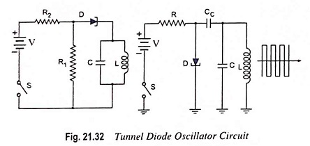
A practical circuit of a tunnel diode oscillator in two slightly different ways is shown in Fig. 21.32. Here R2 sets the proper bias level for the diode whereas R1 in parallel with the L-C tank circuit sets proper current level for it. The capacitor Cc is the coupling capacitor. As the switch is closed, the tunnel diode is set into oscillations whose frequency is equal to the resonant frequency of the tank circuit.
The tunnel diode operates very fast and it is possible to make tunnel diode oscillators which operate in the microwave frequency region. A tunnel diode has a characteristic with a negative resistance oscillators region between voltages of about 0.1 and 0.3 V and can be used as an oscillator at frequencies up to 100 GHz.