Resistance Heating – Types, Advantages and Applications:
Resistance heating is based upon the I2R effect. This method of heating has wide applications such as heat treatment of metals (annealing, hardening etc.), drying and baking of potteries, stoving of enamelled ware and commercial and domestic cooking. Temperature up to about 1,000°C can be obtained in ovens employing wire resistances for heating elements. There are two methods of resistance heating.
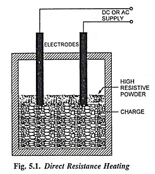
1. Direct Resistance Heating:
In this resistance heating method, the material or charge to be heated is taken as resistance and current is passed through it. The charge may be in the form of powder, pieces or a liquid. Two electrodes are immersed in the charge and connected to the supply in case of availability of direct current or single phase ac supply and three electrodes are immersed in the charge and connected to supply in case of availability of 3-Φ ac supply. When some pieces of metals are to be heated some highly resistive powder is sprinkled over the surface of pieces to avoid direct short circuit. The current flows through the charge and heat is produced. This resistance heating method has high efficiency since heat is produced in the charge itself. As the current in this case is not easily variable, therefore, automatic temperature control is not possible. However, uniform and high temperature can be obtained. This method of heating is used in salt bath furnaces and in the electrode boiler for heating water.
2. Indirect Resistance Heating:
In this resistance heating method, the current is passed through a wire or other high resistance material forming a heating element. The heat proportional to I2R loss produced in the heating element is delivered to the charge by one or more of the modes of transfer of heat viz. conduction, convection and radiation. If the heat transfer is by conduction the resistor must be in contact with the charge. An enclosure, known as heating chamber, is required for heat transfer by radiation and convection for the charge. For industrial purposes, where a large amount of charge is to be heated, the heating clement is kept in a cylinder surrounded by jacket containing the charge.
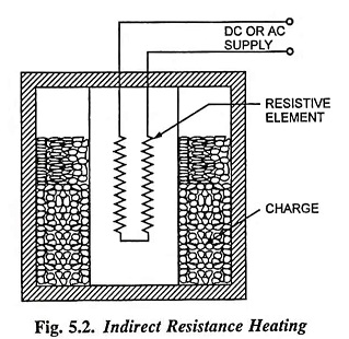
This arrangement provides a uniform temperature. Automatic temperature control can be provided in this case. This resistance heating method is used in room heaters, immersion water heaters and in various types of resistance ovens employed in domestic and commercial cooking, and salt bath furnaces.
Resistance Ovens and Furnaces:
Resistance furnaces may be classified according to their operating temperature. Low temperature heating chamber with provision for ventilation is termed as oven. Resistance ovens are used for drying and baking potteries, drying varnish coatings, vulcanising and hardening of synthetic materials and commercial and domestic heating. They are also employed for tempering hardened steel pieces. Medium temperature furnaces having operating temperatures between 300°C and 1,050°C are employed for annealing, normalising of steel and non-ferrous metals, melting of non-ferrous metals and stove enamelling. High temperature furnaces having operating temperatures between 1,050°C and 1,350°C are employed for hardening applications. Typical furnace using heating elements and having provision of carrying out heating in particular atmosphere is depicted in Fig. 5.3.
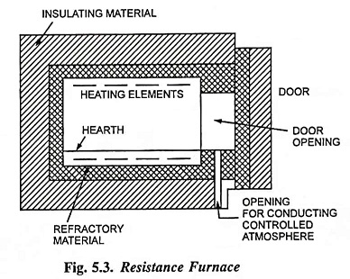
The resistance oven is constructed of firebricks or other heat insulating material supported on a metal framework. The heating elements are mounted on the top, sides or bottom of the oven, according to circumstances.
The resistance furnace is an enclosure with a refractory lining : a surrounding layer of heat insulation and outer casing of steel plate, bricks or tiles. The inside proportions of a heating chamber are made to suit the character of the charge and type of furnace or oven. The nature of material required for the insulation is determined by the maximum temperature of the inner face of the layer of insulation of a heating chamber. The heating elements are mounted on top, sides or bottom of the oven as the circumstances permit.
Heating Chambers:
An enclosure of a charge to be heated by radiation or convection or by the joint effect of these modes of heat transfer is known as heating chamber. Apart from mechanical considerations the design of the chamber is related primarily to temperature and the major mode of heat transfer to be used. The essential features are : the enclosing chambers, the resistors, and the atmosphere within the chamber. The functions of the heating chambers are :
- to control the distribution of heat within the chamber:
- to control the cooling rate of charge, if required:
- to confine the atmosphere around the charge: and
- to store as much of the heat supplied as may be practicable and economical.
A cylinder with an inside diameter equal to its height represents an ideal shape and proportions of a heating chamber, keeping only the utilisation of material and rate of heat loss from the exterior surfaces in view. This ideal is seldom attained because of many practical considerations in heating service. Electric heating permits wide latitude in the proportions and shape of a heating chamber, and factory planning takes this into account in developing the sequence of movements of material through maim factoring operations.
Heating chambers may be of ‘batch’ or ‘continuous’ type. In the former type, the charge remains stationary during the heat application. The cycle may include cooling the charge in the chamber. In case of continuous type chambers, the charge is heated as it moves through the chamber. In some cases the chamber is extended for more or less cooling of the charge before it leaves the chamber.
The application of the batch type heating chamber is defined by the following conditions.
- Intermittent production.
- Long period of heating and in some cases slow cooling.
- For material that cannot be handled on conveyors.
- Heating service beyond the range of the capacity of conveying mechanisms.
- Supplementary heating service.
A continuous type heating chamber is used where the flow of material is reasonably uniform and continuous, i.e., mass production conditions. In some cases batch heating chambers with automatic charging and discharging are essentially of the continuous type.
Heating Element Materials:
A material which is used as a heating element must possess the following properties :
- High resistivity: The material to be used for heating element should be of high specific resistance so that a small length of wire may be sufficient to produce the required amount of heat.
- High melting point: Melting point of material to be used for heating element should be high so that charge can be heated to a high temperature.
- Low temperature coefficient: The material for heating element should have low temperature coefficient so that resistance may not vary with the change in temperature otherwise starting current would be high.
- Free from oxidation: The material for heating element should be such that it may withstand the required temperature without getting oxidised, otherwise it would have to be replaced frequently.
The materials commonly used for heating elements for low and medium temperature services are either alloy of nickel and chromium (Nickel 80% and chromium 20%) or alloy of nickel, chromium and iron (Ni 65%, Cr 15% and Fe 20%). The addition of iron of the alloy reduces the temperature at which oxidation takes place but the cost of the product is also reduced.
Ni-Cr alloy is suitable for temperatures up to 1,150°C and for work in severe conditions Ni-Cr-Fe alloy is recommended for use up to 950°C. Nickel-chromium (Nichrome) alloy has not only good resistance to oxidation up to 1,150°C but at the same time it has sufficient strength. Ni-Cr-Fe alloy is the cheapest, and most economical and stronger for temperatures up to 950°C. Alloys containing iron, chromium, cobalt and aluminium can withstand temperatures as high as 1,350°C.
Nickel-copper alloy (Eureka or constantan by trade name) is often employed for heating elements operating at low temperatures. Its most important property is that it has virtually zero resistance temperature coefficient. Iron-chromium-aluminium alloy (Kanthal by trade name) has very good resistance to oxidation at high temperatures but are weaker in mechanical strength and, therefore, such elements need more support.
Resistors for operating temperatures above 1,150°C are made of silicon carbide, molybdenum, tungsten and graphite.
Silicon carbide is the basis of a resistor material for operating in air for temperatures up to about 1,500°C. The material is formed into rods of diameters and lengths for combination into circuits of the required electrical rating. The range between the cold and hot resistances is small enough to permit single voltage operation. The resistance gradually increases with use, and an auto-transformer with taps to compensate for this increase of resistance is desirable.
Molybdenum resistors are suitable for temperatures up to 1,650°C. This metal is ductile enough at room temperature for drawing into wire for resistor windings. The wide range between the cold and hot resistances makes multiple voltage operation necessary. The supports (insulators) of the winding should be magnesia or zirconia. Molybdenum resistors cannot be operated in air and also must be protected against reactions with silicon and carbon. The metal is immune from reactions with sulphur, nitrogen, hydrogen, and water vapour. A hydrogen atmosphere is usually used for the protection of these resistors. Molybdenum is not suitable for resistors of vacuum furnaces because of its high vapour pressure.
Tungsten resistors can be used for temperatures up to 2,000°C. The maximum temperature is limited by the refractory supports of the resistor. The metal must be heated for drawing into shapes. The low vapour pressure of tungsten makes it useful for resistors of vacuum furnaces.
Graphite resistors are suitable for any temperature that can be used. The resistors require protection against oxidation above about 600°C. Also because of the chemical activity of carbon, special consideration must be given to the surrounding atmosphere. The material is available in a wide range of shapes and dimensions.
Maximum Operating Voltage:
Maximum operating voltage is limited, by electrical insulation at high temperatures and from safety consideration, to 600 volts. This value may exceed in special cases. Resistor winding may be in one, two or more circuits and may be connected either to single or to polyphase supply system.
Design of Heating Element:
Knowing the electrical input and its voltage the size and length of the wire required as the heating element to produce the given temperature can be calculated. The wire employed may be circular or rectangular like a ribbon. The latter permit the use of higher wattage per unit area and are used in ovens, vulcanizers, toasters etc. The heating element on reaching a steady temperature will dissipate the heat from its surface equivalent to electrical input. Since generally the heat will be dissipated from the heating elements at high temperatures, it is reasonable to assume that the whole of the heat energy is dissipated solely by radiation.
Heat dissipated according to Stefan’s law,
Electrical input,

where
- V is the supply voltage and
- R is resistance of heating element and is given by the expression,

for a circular wire of diameter d, length l and resistivity ρ.
Electrical power input,
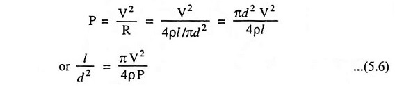
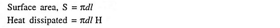
Since at steady temperature
Solving Eqs. (5.6) and (5.7) length and diameter of wire can be determined.
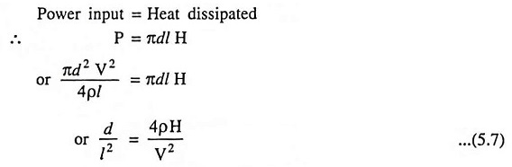
For ribbon type of conductor let w be the width and t be the thickness.
Electrical power input,
Since at steady temperature
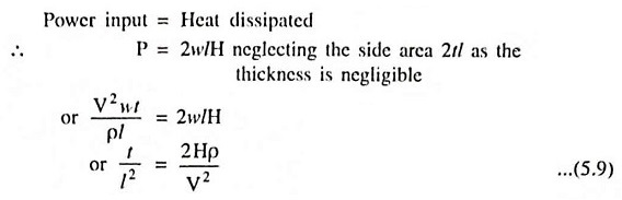
So by solving the two Eqs. (5.8) and (5.9), length l and width w for a ribbon of thickness t will be evaluated.
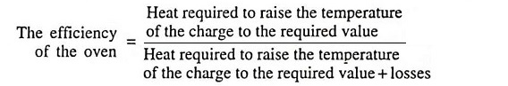
Efficiency and Losses:
The heat produced in the heating elements is also to overcome the losses occurring due to
- heat used in raising the temperature of oven or furnace;
- heat used in raising the temperature of the containers or carriers;
- heat conducted through the walls;
- escapement of heat due to opening of door; in addition to heat required to raise the temperature of the charge to the required value.
The heat required to raise the temperature of the charge to the required value, W = Mass of charge in kg x specific heat of charge in J/kg/°C x temperature rise = mst Joules.
The heat used for raising the temperature of the oven or furnace can be calculated in a similar way by knowing the weight of the refractory material and its specific heat. In case the oven is used continuously this loss becomes negligible.
Heat used for raising the temperature of container is calculated in exactly the same way as for oven or furnace. The container usually has to be heated up afresh for each charge.
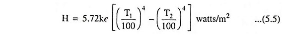
Since the heat is continuously conducted through the walls, this source of heat loss is most important. It can be determined knowing the mean value of the inside and outside surface areas A in square metres; the thickness of walls t in metre; inside and outside temperatures T1 and T2 in °C and thermal conductivity of walls k in MJ per hour per square metre, per metre, from the following expression
Heat loss by conduction through walls

Though there is no specific formulae for determination of loss occurring due to opening of door for inspection of the charge, however, this loss may be taken as 0.575 to 1.15 MJ/m2 of the door area if the door is opened for a period of 20 to 30 seconds.
The efficiency defined above lies between 60 and 80 per cent. A more convenient figure for expressing the behavior of an oven, however, is the energy required per tonne of charge treated. Typical values for different processes are given in Table 5.1.

Temperature Control of Resistance Ovens/Furnaces:
Temperature control is necessary in resistance ovens/furnaces temperature may have to be kept constant or varied according to requirements. Control may be manual or automatic.
In resistance ovens/furnaces heat developed depends upon I2R t or V2/R t. So there are three ways in which the temperature can be controlled. Firstly, by varying the applied voltage to the elements or current flowing through the element; secondly, by varying the resistance of elements and thirdly, by varying the ratio of on and off times of supply.
Voltage across the oven can be controlled by changing the transformer tappings. This is economical and most suitable if the transformer is to be used for stepping down the voltage for supply to ovens or furnaces, but such conditions do not arise usually. Auto-transformer or induction regulator can also be used for variable voltage supply. In case of large furnace, there may be an independent generating set for the supply to the furnace and in that case variable voltage supply can be provided.
Alternatively voltage across the oven or furnace can be controlled by varying the impedance connected in series with the circuit. But this method is not economical as power is continuously wasted in the controlling resistance. Its use is, therefore, limited to small furnaces.
Temperature can also be controlled by switching the various combinations of groups of resistances used in the ovens or furnaces in the following ways.
- Use of Variable Number of Elements: In this method, the number of heating elements in working are changed; so total power input or heat developed is changed. This method does not provide uniform heating unless the number of heating elements in the circuit at any particular instant are distributed over the surface area, which requires complicated wiring.
- Change of Connections: In this method the elements are arranged to be connected either all in series or all in parallel or combination of both or in star or in delta by means of switches at different instants according to the requirements. This is the simplest and most commonly used method of control.
An on-off switch can also be employed for temperature control but its use is restricted to small ovens. The time duration for which the oven is connected to the supply and the time duration for which it remains cut off from supply will determine the temperature. Here an oven is supplied through a thermostat switch which makes and breaks the supply connections at particular temperature. The ratio of Time duration during which supply remains on/Total time duration of an on-off cycle is an indication of temperature. The higher the ratio, the larger will be the temperature of the oven. Advantage of this method is that it is more efficient than series impedance method.
Normally the temperature is required to be maintained between limits. This necessitates some type of automatic control of the thermostat type. When the temperature of the oven exceeds or falls below certain predetermined values, the thermostat connected in the circuit operates a relay which varies the current in the elements by any one of the methods given above. The relay may even switch the oven out of service if so required. The actual switching is carried out by contactors.
For large capacity ovens, some protection is to be provided against overloading, excessive temperatures, and in some cases against the possibility of workmen loading or unloading the furnace with the power on.
The only possibility of overload is due to a part of a metallic charge falling against and short circuiting the elements. An instantaneous overload relay is provided and set to trip the circuit at 10 or 15 per cent, above normal current. This adequately guards against damage due to such a contingency. In addition to above, fuses are also provided either in the main oven circuit or in the hold-on coil of the energizing contactors to provide protection in case of failure of automatic control system. For the protection of nickel-chrome wire in this way a gold fuse is employed, because it has a sharp melting point of 1,060°C; and does not oxidise. Fuses melting at a lower temperature can be had, but although of some service are not completely reliable.
Causes of Failure of Heating Elements:
The chief causes of failure of heating elements are given below.
- Formation of Hot Spots: Hot spots are the points in the heating element which are at a higher temperature than the main body of the element. One of the reasons of formation of hot spot in the heating element is high rate of local oxidation that may reduce the element wire x-section, thereby increasing the resistance at that spot and producing more heat locally and causing breakdown of the element. Another reason may be due to shielding of element by supports etc. that will reduce the local heat loss by radiation and cause an increase of temperature of shielded portion of the element. However, it can be minimized by using minimum number of supports without producing distortion of the element. Other causes are due to too high element temperature, insufficient support for the element or selection of wrong fuse material, may result in sagging and warping of the material. The sagging and warping may cause uneven spacing of sections, thereby developing hot spots where sections are closest together or even there may be actual shorting of adjacent sections of an element.
- Oxidation and Intermittency of Operation: Continuous and tenacious oxide scale is formed on the surface of the heating element when it attains high temperature. This oxide layer is so strong that it prevents further oxidation of the inner metal of the heating clement. But in case of frequent use of the element, the scale is subjected to thermal stresses developed owing to frequent heating and cooling, The oxide scale, therefore, cracks and flakes off, exposing further fresh metal to oxidation and thus resulting in increased local oxidation and producing hot spots.
- Embrittlement Due to Grain Growth: All heating alloys containing iron tend to form large brittle grains at high When cold, the heating elements are very brittle and liable to rupture easily on slighest handling and jerks.
- Contamination and Corrosion: Gases of the controlled atmosphere prevailing in annealing furnaces or fumes from flux used in brazing furnaces, or oil fumes caused by heat treatment of components contaminated with lubricant contaminate the elements and produce dry corrosion.
Of all the conditions stated above, which determine the element life, most critical are the temperature of the hottest point and ratio of intermittent to continuous working.
Special Types of Resistance Furnaces:
The most important applications of resistance ovens are air-circulation oven and bright annealing furnace.
- Air-Circulation or Convection Type Furnaces: The charge may not get uniformly heated in an ordinary furnace in which heat is transferred to the charge almost entirely by radiation. If uniform distribution of heat is necessary and the temperature is not to exceed about 600°C, such furnaces are used. The common applications are drawing and hardening of steel, heat treatment of aluminium and light metals. In such furnaces, air is passed over the heating elements and this heated air is circulated over or through the charge imparting its heat uniformly to all parts of the charge by conduction. The direction of flow in air-circulation furnaces is sometimes reversed periodically in order to make the distribution of heat more uniform. If this were not done, the temperature of that part of the charge which comes across the hot air first, will be higher than that which comes across it afterwards. However, this difference can be minimised by circulating large volume of air. Blowers and fans are used for circulating the gas or air. The advantage of the circulating air or gas is to impart all the parts of the charge a uniform application of the atmosphere. Generally the charge is to be cooled in the furnace itself and to achieve this gases are circulated after being cooled. Gases are let through cooling pipes during the cooling process. Nitriding is an important application. In this process the steel after being heated by hot air, is exposed to ammonia. The steel absorbs nitrogen and gets hardened. An important item in the design of such an oven is the characteristic of the fan. A centrifugal fan is used, but it must be of such a design that a change in the resistance of the air path due to charges of different size and shape does not appreciably affect the volume of air delivered or kW required by the motor.
- Resistance Furnace For Bright Annealing: The process of cooling a heated job slowly for removing its brittleness is known as annealing. In the usual process of annealing the job is left covered with a scale of oxide which must be removed in order to have bright finish. The formation of oxide scale can be prevented if annealing process is carried out in an atmosphere free from oxygen, water vapour and carbon dioxide. Such a condition can be achieved by heating the job in an air tight furnace to which is connected a non-return air valve. During the period of heating air and any oil absorbed by the job are expelled through the non-return valve due to their expansion. During cooling the non-return valve closes, thereby preventing access of oxygen or other gases to the job. Thus the surface of the job under annealing process is maintained bright.
Salt-bath Heating:
Salt-bath furnaces are used for the purposes of tempering, quenching and hardening of steel tools. The characteristics of salt-bath heating are rapidity and uniformity and selective localised heating combined with protection from oxidation.
This type of furnace consists of a bath of some salt such as molten sodium chloride and two electrodes immersed in it. When the current between electrodes immersed in the salt is passed, heat is developed and the temperature of the salt bath may be in the range between 1,000°C and 1,500°C depending upon the type of salt used. In this bath the material to be heated is dipped and the necessary heat treatment, as required for tool steel, is given to it. The heat transfer in this case is by conduction and by better contact of the body with the heated salt, which is in molten state.
As dc would cause electrolysis of the salt, therefore, alternating current is used. The voltages up to 20 volts and currents up to 3,000 amperes depending on the size of the furnace are used. Voltage on the secondary side is changed by tap changing gear included in the primary of the transformer.
The resistance of the salt decreases with the increase of temperature of the salt therefore, in order to maintain constant power input it is necessary that the salt furnaces are started with highest tap and as the temperature rises, this is gradually brought to lower taps. Control of power input is also affected by varying the depth of immersion and distance between electrodes. It must be ensured that the current flows through the salt and not through the job being heated.
Infrared or Radiant Heating:
In the ordinary resistance furnaces the heat is transferred from heating elements to the charge partly by radiation and partly by convection, the latter predominating at low and medium temperatures but in this form of heating suitable for low and medium temperature heating purely radiant or infrared heating is used. In this method of heating, heating elements consist of tungsten filament lamps together with reflectors to direct the whole of the heat emitted on to the charge. The lamps are operated at 2,300°C instead of 3,000°C giving greater proportion of infrared radiation and a longer life. The reflectors are plated with rhodium which, being harder, has a longer life and is easier to maintain. The lamps employed are usually of rating between 250 and 1,000 watts operating at 115 volts. The operation at low voltage results in a robust filament.
Plant sizes range from a single lamp to chambers containing several hundred kW of lamps. With this arrangement charge temperature between 200°C and 300°C can be obtained. Heat emission intensities up to 7,000 watts/square metre of the chamber surface can be obtained. These are much higher than those obtained with ordinary resistance ovens (1,500 watts/ m2). In radiant heating heat absorption remains practically constant whatever the charge temperature is where as it falls off rapidly as the temperature of charge rises in the ordinary resistance furnace.
In this process the lamps with their reflectors are grouped close together to form the walls and possibly the top of a heating chamber: the lamps being mounted on a light angle-iron framework, no heat insulation is required as all heat is directed inwards. Individual reflectors for each lamp or trough reflectors may be used, the latter enabling a greater number of lamps to be installed in the given area. The precise shape of the chamber depends on the size and shape of the charge to be heated and the framework can easily the made adjustable. Continuous processes can be had, by carrying the articles to be heated through the chamber on a conveyor belt.
Advantages of Infrared Heating:
Infrared heating possesses the advantages of (i) rapid heating, (ii) compactness of heating units, (iii) flexibility and (iv) safety and finds application in (i) paint stoving (ii) drying of wood furniture (iii) preheating of plastics prior to moulding (iv) softening of thermoplastic sheets and (v) drying of pottery, paper, textiles etc. where moisture content is not large.
For obtaining best results, the infrared lamps should be located at a distance of 25-30 cm from the object to be heated.