Single Phase Half Wave Controlled Rectifier with Resistive Load and Inductive Load:
In a Single Phase Half Wave Controlled Rectifier only one SCR is used in the circuit. It is included in between the ac source the load. The transformer is used on the supply side in order to change the voltage level to suit the requirements. The performance of the controlled rectifier very much depends upon the type and parameters of the output (load) circuit.
Single Phase Half Wave Controlled Rectifier with Resistive Load:
Figure 27.1 (a) depicts the circuit diagram of a Single Phase Half Wave Controlled Rectifier with resistive load (triggering circuit not shown in the figure). The circuit is energized by the line voltage or transformer secondary voltage, ν = Vmax sin ωt. It is assumed that the peak supply voltage never exceeds the forward and reverse-blocking ratings of the thyristor. The thyristor can be triggered at any angle α in the positive half cycle and thus the output voltage can be controlled. The thyristor blocks during the negative half cycle. The various voltage and current waveforms for the Single Phase Half Wave Controlled Rectifier with resistive load circuit are shown in Fig. 27.1 (b).
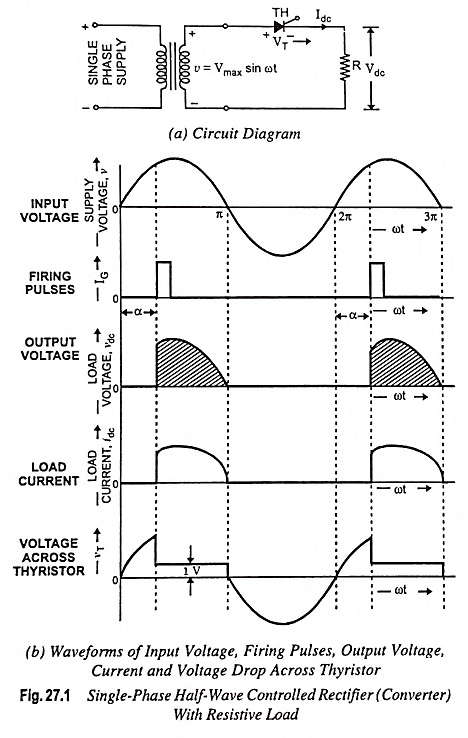
During the positive half cycle of the supply voltage, the thyristor anode is positive w.r.t, its cathode and until the thyristor is triggered by a proper gate pulse, it blocks the flow of load current in the forward direction. When the thyristor is fired at an angle α, full supply voltage (ignoring the thyristor drop VT) is applied to the load. Thus, the load is directly connected to the ac supply. With a zero reactance source and a purely resistive load, the current waveform after the thyristor is triggered will be identical to the applied voltage wave and of a magnitude dependent on the amplitude of the applied voltage and the value of the load resistance R. At zero crossing, the thyristor is turned off by natural commutation thereby switching off the power to the load. The voltage and current are in same phase, as illustrated in Fig. 27.1 (b). The angle (π – α) during which the thyristor conducts is called the conduction angle. By varying the firing angle α, the output voltage can be controlled. During the period of conduction, voltage drop across the thyristor is of the order of one volt. During the negative half cycle of the supply voltage, the thyristor blocks the flow of load current and no voltage is applied to the load R.
Analysis : Average load voltage is given by
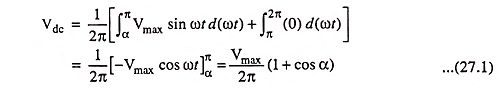
where Vmax is the peak value of the ac input voltage.
From the above Eq. (27.1) it is obvious that the load voltage varies with firing angle α having extremes values for α = 0 and α = π or 180°. The maximum output voltage is obtained when α = 0 and is given by
![]()
Average load current, with resistive load, is directly proportional to the average load voltage and is given by

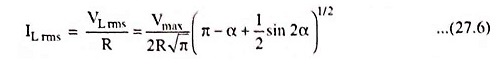
The rms value of load voltage is given by
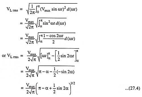
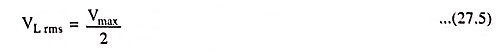
For firing angle α = 0
RMS value of load current,
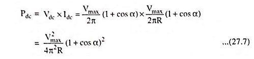
Average output power is given by
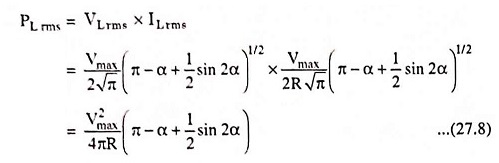
RMS value of output power is given by
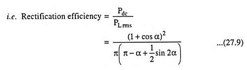
Rectification efficiency is defined as the ratio of average output power, Pdc and the output ac power which is equal to rms value of output power PL rms
Transformer utilization factor (TUF) is defined as the ratio of average output power Pdc and VA rating of transformer (Vrms x Irms) i.e.
The output of a rectifier is not a pure sinusoidal wave—it contains harmonics present in the output which are responsible for generation of heat in the load.
Single Phase Half Wave Controlled Rectifier with Inductive Load:
If the load consists of a resistance and inductance then the output current waveform will be different from that obtained with a pure resistive load. The circuit diagram for a Single Phase Half Wave Controlled Rectifier with R-L load is shown in Fig. 27.2 (a). The circuit is the same as that of Fig. 27.1 (a) except that the load in this case is a combination of resistance and inductance. The waveforms for voltage and current of Single Phase Half Wave Controlled Rectifier with an inductive load are shown in Fig. 27.2 (b).
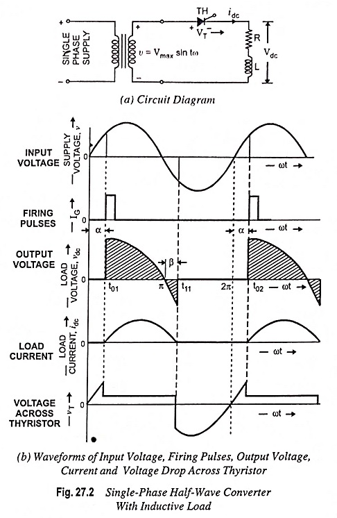
At the instant t01, when the thyristor is triggered, the load current will increase gradually, due to inductive nature of load, in a finite time. The supply voltage from this instant appears across the load. Energy is stored in inductor during time interval from t01 to π. At the time instant π, the supply voltage reverses, but the thyristor keeps conducting. This is due to the fact that current through the inductance cannot be suddenly reduced to zero. During negative voltage half cycle, current continues to flow till the energy stored in the inductance is dissipated in the load resistor and a part of energy is supplied back to the source. As the current reaches zero, the thyristor is turned off automatically and regains its blocking capability. Thus, due to energy stored in inductor, current continues to flow up to instant t11. At time instant t11, the load current become zero and the thyristor turns off.
At the time instant t02, when again pulse is applied, the above cycle repeats. Hence the effect of the inductive load is increase in the conduction period of the SCR.
The half-wave circuit is not normally used since it produces a large output voltage ripple and is incapable of providing continuous load current.
The average value of load voltage can be derived as

assuming that in negative half cycle the thyristor conducts for a period of β = α
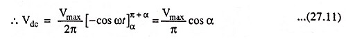
Comparing Eqs. (27.2) and (27.11) it is revealed that average load voltage is reduced in case of inductive load.
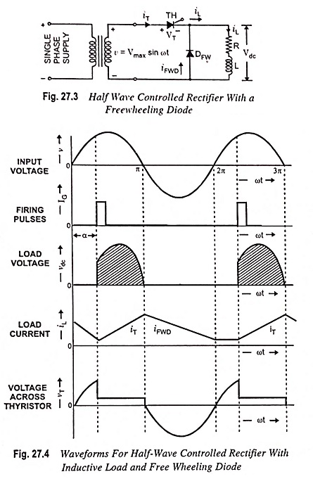
Effect of Freewheeling Diode:
Figure 27.3 depicts a freewheeling diode DFW connected across a load. Freewheeling diode, also sometimes known as bypass diode or commutating diode, is used to improve the waveshape of the load current and power factor. Freewheeling diode DFW allows for dissipation of energy stored in the inductance of the load and provide for continuity of load current when the thyristor is blocked. With flywheel diode, thyristor will not be able to conduct beyond 180°.
The freewheeling diode serves main two functions :
- It prevents reversal of load voltage except for small diode voltage drop.
- It transfers the load current away from the main rectifier, when input voltage reverses the cycle.
The load voltage and current waveforms are depicted in Fig. 27.4.
The voltage induced in the inductance, during the positive half cycle, will change its polarity as the di/dt changes its sign and freewheeling diode DFW will start conducting as soon as the induced voltage is of sufficient magnitude, thereby enabling the inductance to discharge its stored energy into the resistance.
Thus, after 180°, the load current will freewheel through the diode and a reverse voltage will appear across the thyristor. The power flow from the input occurs only when the thyristor is conducting. In the absence of freewheeling diode, during the negative half cycle of the supply voltage, the thyristor returns the energy stored in the load inductance to the supply mains. With the freewheeling diode the freewheeling action takes place and no power is returned to the supply source. Hence, the ratio of the reactive power flow from the input to the total power consumed by the load is reduced for the phase-control circuit with a freewheeling diode. It means that the input power factor is improved with the use of freewheeling diode.