Half and Full Wave Rectifier Circuits:
Half and Full Wave Rectifier Circuits for producing high d.c. voltages from a.c. sources may be
(a) Half wave,
(b) Full wave, or
(c) Voltage doubler type rectifiers.
The rectifier may be an electron tube or a solid state device. Nowadays single electron tubes are available for peak inverse voltages up to 250 kV, and semiconductor or solid state diodes up to 20 kV. For higher voltages, several units are to be used in series. When a number of units are used in series, transient voltage distribution along each unit becomes non-uniform and special care should be taken to make the distribution uniform.
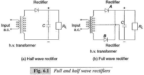
Commonly used Half and Full Wave Rectifier Circuits are shown in Fig. 6.1. In the half wave rectifier (Fig. 6.1a) the capacitor is charged to Vmax, the maximum a.c. voltage of the secondary of the high voltage transformer in the conducting half cycle. In the other half cycle, the capacitor is discharged into the load. The value of the capacitor C is chosen such that the time constant CRL is at least 10 times that of the period of the a.c. supply. The rectifier valve must have a peak inverse rating of at least 2 Vmax. To limit the charging current, an additional resistance R is provided in series with the secondary of the transformer.
A full wave rectifier circuit is shown in Fig. 6.1b. In the positive half cycle, the rectifier A conducts and charges the capacitor C, while in the negative half cycle the rectifier B conducts and charges the capacitor. The source transformer requires a centre tapped secondary with a rating of 2V.
For applications at high voltages of 50 kV and above, the rectifier valves used are of special construction. Apart from the filament, the cathode and the anode, they contain a protective shield or grid around the filament and the cathode. The anode will be usually a circular plate. Since the electrostatic field gradients are quite large, the heater and the cathode experience large electrostatic forces during the non-conduction periods. To protect the various elements from these forces, the anode is firmly fixed to the valve cover on one side. On the other side, where the cathode and filament are located, a steel mesh structure or a protective grid kept at the cathode potential surrounds them so that the mechanical forces between the anode and the cathode are reflected on the grid structure only.
In modern high voltage laboratories and testing installations, semiconductor rectifier stacks are commonly used for producing d.c. voltages. Semiconductor diodes are not true valves since they have finite but very small conduction in the backward direction. The more commonly preferred diodes for high voltage rectifiers are silicon diodes with peak inverse voltage (P.I.V.) of 1 kV to 2 kV. However, for laboratory applications the current requirement is small (a few milliamperes, and less than one ampere) and as such a selenium element stack with P.I.V. of up to 500 kV may be employed without the use of any voltage grading capacitors.
Both Half and Full Wave Rectifier Circuits produce d.c. voltages less than the a.c. maximum voltage. Also, ripple or the voltage fluctuation will be present, and this has to be kept within a reasonable limit by means of filters.
Ripple Voltage with Half and Full Wave Rectifier Circuits:
When a full wave or a half wave rectifier is used along with the smoothing capacitor C, the voltage on no load will be the maximum a.c. voltage. But when on load, the capacitor gets charged from the supply voltage and discharges into load resistance RL whenever the supply voltage waveform varies from peak value to zero value. These waveforms are shown in Fig. 6.2. When loaded, a fluctuation in the output d.c. voltage δV appears, and is called a Ripple.
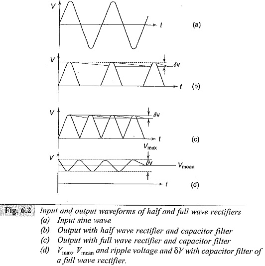
The ripple voltage δV is larger for a half wave rectifier than that for a full wave rectifier, since the discharge period in the case of half wave rectifier is larger as shown in Fig. 6.2. The ripple δV depends on
(a) the supply voltage frequency f,
(b) the time constant CRL, and
(c) the reactance of the supply transformer XL.
For half wave rectifiers, the ripple frequency is equal to the supply frequency and for full wave rectifiers, it is twice that value. The ripple voltage is to be kept as low as possible with the proper choice of the filter capacitor and the transformer reactance for a given load RL.