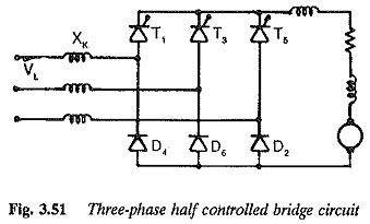
Three phase half controlled bridge circuit:
This is obtained by a series connection of a 3 pulse controlled converter and a 3 pulse uncontrolled one. The three arms of the former consist of thyristors and the three arms of the latter comprise diodes. A typical Three phase half controlled bridge circuit is shown in Fig. 3.51. Here the controlled converter is shown with a common cathode connection and forming the positive group. The uncontrolled one has a common anode connection and forms the negative group. It is also possible to have the converter with connections the other way around. The thyristors commutate at the phase angle at which they are fired. The diodes commutate at the natural firing instant α = 0. The thyristors conduct for 120° and are fired at intervals of 120°. The output voltages of the two converters are added to get the net output voltage at the dc terminals. The firing angle of the controlled converter ranges from 0 to 180° (under ideal conditions). The output voltage is varied from a positive maximum to a negative maximum. The average value of the voltage for the uncontrolled converter is fixed at the maximum value of the controlled one. The net voltage at the dc terminal varies from a positive maximum to zero. In practice, due to the inverter limit of the controlled converter, the voltage cannot go to zero.
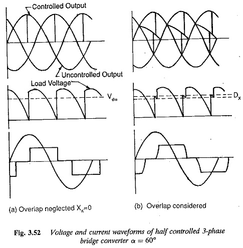
A thyristor and a diode conduct at any given time the diode is forward biased at the natural firing instant. A thyristor conducts, even if it is reverse biased, until the next thyristor in the sequence is fired. Thus there is a natural free wheeling of the load current via the incoming diode and outgoing thyristor. The load voltage is zero during the free wheeling period. Free wheeling due to conduction of diode does not allow negative excursions of load voltage. This reduces the ripple content in the output voltage. The ripple frequency of the output voltage at α = 0 is 6f. For α < 60°, free wheeling does not take place since the voltage is always positive on the dc side. The negative instantaneous value does not occur. Free wheeling takes place only when α ≥ 60°. The ripple frequency decreases to 3f at these firing angles (α ≥ 60°). The ripple voltage is less at a = 60° and it increases for α > 60°. Compared to a fully controlled converter, the smoothing inductance required is large at α = 90°, even though there is inherent free wheeling.
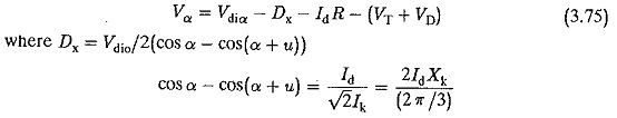
The average values of dc voltage can be obtained as (Fig. 3.52)
![]()

Considering the voltage drops due to the reactances (overlap), resistances and the device drops, the dc voltage in the operating region
The voltage and current waveforms of the converter at different firing angles are shown in Fig. 3.52. The line current waveforms show that the period of the current pulse decreases in the line as the firing angle is increased. The effective values of the fundamental as well as the harmonics depend upon the firing angle. The value of g depends on the firing angle; it is not constant, as in the case of a fully controlled converter. All the harmonics can be referred to the mean value of dc current. Hence with larger delay angles, the effective value of line current is much smaller than at α = 0. However the effective value of the harmonics is much larger at greater delay angles, and becomes a large percentage of the input current.
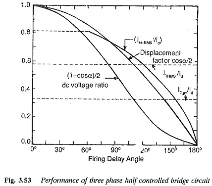
The fundamental displacement factor is cos(α/2). The total power factor is g cos(α/2). Where g is the ratio of the fundamental rms current to the total rms current. From the current waveforms, we get

The rms value of current
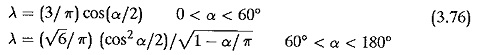
There is a saving of control reactive power but not of commutation reactive power. The power ibctor as a function of Vdiα/Vdio is depicted in Fig. 3.53. An improvement in the power factor can be seen in the range 0° < α < 180°. The value of g is the same as for a fully controlled converter in the range 0 < α < 60°.
The peak forward and reverse voltage of the thyristors and diodes is √2VL where VL is the rms line to line voltage. The thyristor current is 0.45 VL/R. The rms value of the thyristor and diode currents is
![]()
For highly inductive loads and small firing angles the converter shows the phenomenon of half waving. This can be prevented by means of the FWD across the load.
General features of Three phase half controlled bridge circuit:
When only unidirectional applications are involved it is advantageous to use Three phase half controlled bridge circuit as they provide the following special features over two quadrant converters:
1. The converters are economical as half the positions are occupied by
2. The firing circuit provides signals only to half the number of thyristors and therefore are simple and less costly.
3. The performance of the converter on the line improves as the power factor improves. The control reactive power is less. This is because the period of conduction of the input current pulse decreases as a The input current is zero when the voltage is zero. Thus the reactive power requirement becomes less. There is no saving in commutation reactive power.
4. The voltage variation is between a maximum value and (near about) zero when the firing angle varies from 0 to 180°. However the inverter limit does not allow a to equal 180° and hence the voltage cannot go to Zero output voltage can be obtained by supplying the component converter with different voltages. The converter transformer having two secondaries of appropriate turns feeds the converters. The voltage supplied to the controlled portion is 10% larger than that supplied to the uncontrolled one.
5. The amplitude of ripple decreases and hence the amount of smoothing inductance required is less. This is because natural free wheeling does not allow negative excursions of voltage.
6. The ripple frequency is half that of a fully controlled converter (3-phase converters).