Two pulse bridge converter:
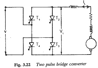
A two pulse bridge converter is achieved as shown in Fig. 3.22 from two midpoint converters. They are connected in series on the dc side and in parallel on the ac side, It is also a single phase converter. At any given time two diagonally opposite thyristors conduct, one thyristor acting as a return path for the current, e.g. T1 conducts the current to load whereas T4 returns the current to the supply. In the next half cycle T2 and T3 take over the jobs of conducting the current as described above.
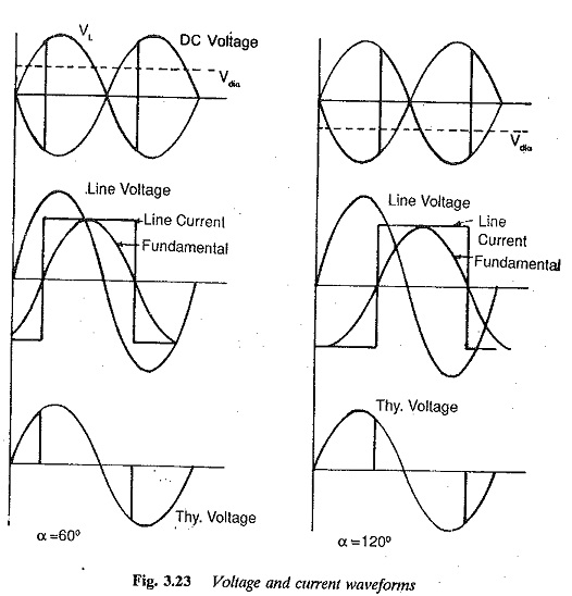
The common point of the transformer is not used as return any more and the input transformer can even be eliminated. The performance of a two pulse bridge converter is similar; to that of a two pulse midpoint converter, but several differences between the two are worth noting. The voltage regulation at the de terminals of the converter due to forward voltage drops of the thyristors is greater, as two thyristors conduct at any time. The control circuitry is slightly more complicated since two channels of gating pulses displaced by 180° are required. The channels must have outputs to provide the firing pulses to the conducting thyristors. The voltage and current waveforms of the converter are depicted in Fig. 3.23 under idealised conditions of instantaneous commutation, smooth dc current, etc.
The average value of the dc voltage in the bridge converter is twice that in a midpoint converter, for the same inverse voltage of the thyristors. This means That the peak forward or reverse voltage of a, thyristor in a bridge converter is just half its value in a midpoint converter, for the same dc voltage at the terminals.
The mean voltage at the dc terminals![]()
where V is the ac voltage. The peak forward or reverse voltage of the thyristors is equal to the peak value of the source voltage = =√2V. In terms of Vdio it is equal to π/2 Vdio. The average thyristor current
![]()
The rms value of the thyristor current
![]()
If a converter transformer is used, its design rating is considerably smaller than that used with a midpoint converter, and is given by![]()
This is because the secondary does not carry any dc in this case. However, the transformer is normally dispensed with as has already been discussed.
As long as the load current is continuous, the voltage can be varied from a maximum of 0.9 V at α = 0° to a minimum of 0 at π/2. When a is retarded further the polarity of the voltage reverses. As the angle is increased towards 180°, the voltage increases in the reverse direction. It reaches a negative maximum at α = 180°. In practice, α = 180° cannot be realized due to overlap and the finite turn off time of the thyristors.
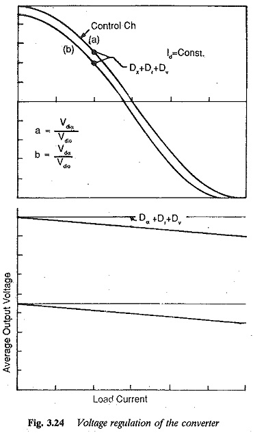
The converter’s voltage regulation, characterised by a reduction of voltage at the dc terminals, can also be attributed to (a) overlap, (b) the resistance drop, and (c) the device drop. The overlap (commutation) affects the voltage regulation in the same way as has been explained earlier for midpoint converters. During commutation the rate of change of current causes a voltage drop across the reactance in series with the thyristors, e.g. transformer leakage reactance, line reactance and any inductive reactance in the circuit to protect from di/dt (Fig. 3.24)
![]()
where
V – ac supply voltage
X1 – per unit reactance in series with thyristor
R – circuit resistance
Id – mean value of load current
VT – forward drop of the thyristor at current Id
The voltage current waveforms, taking overlap into consideration, are depicted in Fig. 3.25.
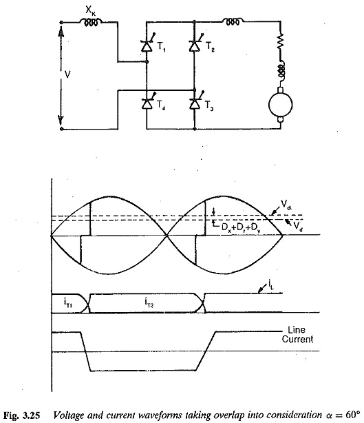
Equations 3.12-3.19 are also applicable to a bridge converter, taking the overlap into consideration. The performance of a bridge converter with respect to the ac ripple superimposing the dc voltage, harmonics in the input current, power factor, reactive power requirement, and discontinuous condition lay out of smoothing reactor, is the same as that of a midpoint converter.
Even though a large number of thyristors are required in the case of a bridge connection, the voltage rating is just half that of a midpoint converter. This may offset the cost of the converter. The characteristics of the converter are given in Fig. 3.26.
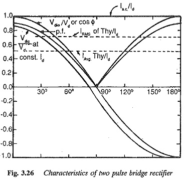
Two pulse bridge converter have a limited power capability, since they are basically single phase converters. The ripple content in the output voltage is large and the amount of inductance required to smooth it, as well as to avoid discontinuous conduction is rather large. Further, a two pulse midpoint converter requires a special type of converter transformer. They therefore find application only under special circumstances.