Pulse Code Modulation(PCM):
Pulse Code Modulation(PCM) is different from the other forms of pulse modulation studied so far, PCM also uses sampling techniques, but it differs from the others in that it is a digital process. Instead of sending a pulse train capable of continuously varying one of the parameters, the PCM generator produces a series of numbers or digits (hence the name digital process). Each one of these digits, almost always in a binary code, represents the approximate amplitude of the signal sample at that instant. The approximation can be made as close as desired.
Principle of PCM:
In PCM, the total amplitude range which the signal may occupy is divided into a number of standard levels, as shown in Fig. 18.16. Since these levels are transmitted in binary code, the actual number of levels is a power of 2, 16 levels are shown here for simplicity, but practical systems use as many as 128. By a process called quantitizing, the level actually sent by any sampling time is the nearest standard (as Quantum) level.
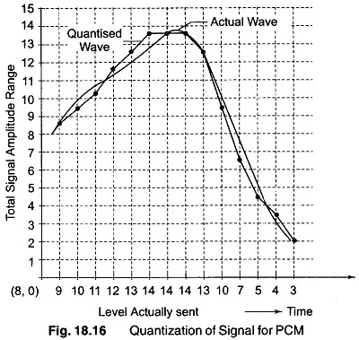
As shown in Fig. 18.16, should the signal amplitude be 6.8 V at any time, it is not sent as a 6.8 V pulse, as it might have been in PAM, nor as a 6.8 µs wide pulse as in PWM, but simply as the digit 7, because 7 V is the standard amplitude nearest to 6.8 V. Furthermore, the digit 7 is sent at that instant of time as a series of pulses corresponding to the number 7. Since there are 16 (24) levels, 4 binary places are required; the number becomes 0111 and can be sent as OPPP, where 0 = no pulse and P = pulse.
Actually, it is often sent as a binary number back-to-front, that is, as 1110 or PPPO, to make demodulation easier.
As shown in Fig. 18.16, the signal is continuously sampled, quantized, coded and sent, as each sample amplitude is converted to the nearest standard amplitude and into the corresponding back-to-front binary number. If sufficient quantizing levels are used, the result cannot be distinguished from that of analog transmission.
A signaling bit is generally added to each code group representing a quantized sample. Hence, each group of pulses denoting a sample here is called a word, expressed by means of (n + 1) bits, where 2n is the selected number of standard levels.
If the actual signal is compared with the signal in Fig. 18.16, it is seen immediately that the quantizing process introduces some distortion. This is quantizing noise, also called noise, because the errors are random in character. The randomness occurs simply because the difference between the digit sent and the actual signal at that instant is completely unpredictable, that is, random.The largest error that can occur is equal to half the size of the sampling interval.
An obvious method of reducing quantizing noise is to increase the number of standard levels until the noise level becomes acceptable. However, more levels require more bits to sent them. The bandwidth required is proportional to the number of bits sent per second. In practical systems, 128 levels for speech are considered quite adequate.
Generation of Pulse Code Modulation
The generation of PCM is a complex process. Essentially, the signal is sampled and converted to PAM, the PAM is quantized, encoded and supervisory signals added. Two important terms need to be considered before understanding the generation of PCM.
1. Companding
2. PCM encoding
The quantized staircase waveform (Fig. 18.16) is an approximation to the original waveform. The difference between the two waveforms amounts to noise added to the signal by the quantizing circuit. The mean square quantization noise voltage has a value of
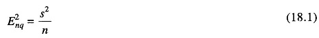
where s is the voltage of each step, or the subrange voltage span. As a result, the number of quantization levels must be kept high, in order to keep the quantization noise below some acceptable limit. For a sinusoidal signal which occupies the full range, the mean square signal voltage is
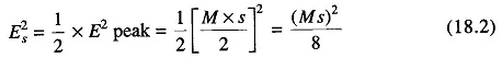
where M is the number of steps and s is the step height voltage. The signal to noise ratio (S/N) for n = 12 bit is now given by
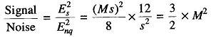
The number of levels M is related to the number of bits per level (n) by M = 2n. Therefore
![]()
1. Companding
The S/N ratio derived above was related to a maximum amplitude signal with a peak to peak voltage equal to the full signal range. In practice, the signal may be many times smaller than this (as much as 30 db less). Since the noise level is dependent on the step size, which is a constant, with small signals a much lower S/N ratio will result. The process of companding is used to overcome degradation of the S/N ratio.
Companding is a compound process of volume compression before transmission, combined with volume expansion after transmission. By itself it does not produce any distortion in the recovered signal, but it does reduce the level of quantization noise during low signal level periods. The compressor amplifies low level signals more than it does high level signals, thus compressing the input voltage range into a smaller span. The steps transmitted have equal amplitude but are equivalent to smaller steps being used in low level signals and larger steps used in high level signals. The result is lower amplitude quantization noise during low level periods.
2. PCM Encoding
The encoding process generates a binary number cor-responding to the quantization level number to be transmitted for each sampling interval. Any one of the codes, such as ASCII or Bi-quinary may be used, as long as it provides sufficient number of symbols to represent all the levels to be transmitted.Ordinary binary coding, in which the binary number corresponding to the decimal number of the level in question is transmitted and most often used. This binary number contains a train of 1 and 0 pulses with a total of log2 N pulses in each number (N is the number of levels in the full range). This system is very economical to realise, because it corresponds exactly to the process of A/D conversion.
Pulse Code Modulation System
The block diagram of a PCM system is shown in Fig. 18.17.
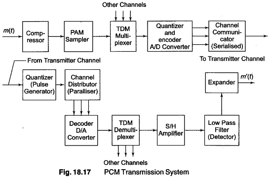
The modulating signal m(t) is applied to the input of the volume compressor unit. A sampling circuit generates a PAM signal from the compressed signals, which is then multiplexed with signals from other input channels. An A/D converter performs the two functions of quantization and encoding, producing a binary coded number for each channel sampling period. A commutator circuit transmits the code bits in serial form.
At the receiver, a two level quantizing circuit reshapes the incoming pulses and eliminates most of the transmission noise. A distributor circuit decommutates the pulses and passes the bits in parallel groups to a D/A converter for decoding. Another distributor demultiplexes the several PAM signals and routes them to the proper output channels. Each channel has an S/ H amplifier which maintains the pulse level for the duration of the sampling period, recreating the staircase waveform approximation of the compressed signal. A low pass filter may be used to reduce the quantization noise and an expander circuit removes the amplitude distortion which was intentionally introduced in the compression of the signal to obtain the output signal m'(t).
The Bell T1PCM system is an example of such an operational system. In this system, 24 voice channels are multiplexed, the sampling frequency being 8 kHz.
The channeling scheme is shown in Fig. 18.18. The frame period is the time interval between successive samples of a given channel, and as seen from Fig. 18.18, the frame period is equal to the sampling period, that is, ts = 1/fs = 1/8 kHz = 125 μs.
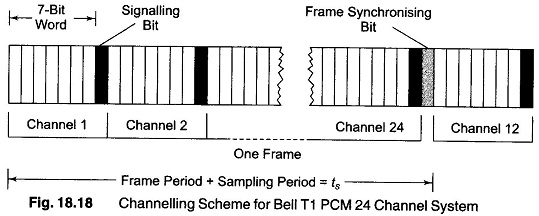
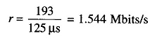
Each channel is coded into 8 bits, which includes signaling information. Therefore, in one frame period the 24 channel requires 24 x 8 = 192 bits.One frame synchronizing bit is also required in each frame period. Therefore, the total number of bits in a frame is 193. The signalling rate is
The most common form of digital transmission is PCM. PCM performs three functions of
(i) sampling the analog signal,
(ii) Quantizing the sampled amplitudes, and
(iii) encoding the quantized sample into a digital system.
Applications of Pulse Code Modulation:
The principle area of PCM application has been in linking relatively close termi¬nals or nearby local exchanges by wire or cable. In due course, PCMs may be employed in very large networks spanning great distances. Figure 18.19 shows a basic block diagram of a Pulse Code Modulation speech terminal.
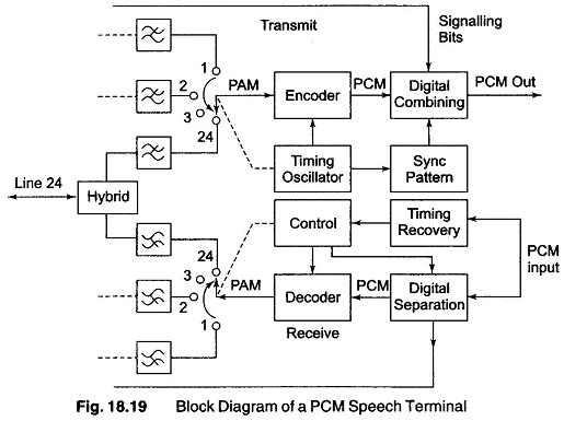
When transmitting, the audio signal is first band limited to minimise aliasing or foldover distortion and then sampled to form a PAM signal. At this point, the signals from all channels go to a common equipment where coding and addition of sync is done. Since each individual channel requires very little equipment, and the more exotic switching and coding is done by common circuitry, Pulse Code Modulation terminals can be inexpensive for a large number of channels.
After sampling, the voltage amplitude is quantized, or forced to take on certain discrete voltages. This new signal forms an approximation to the old one. Because the two forms are not identical, an inherent error occurs. The difference between the old and new signal is called the quantizing error, and is referred to as quantizing noise when heard and measured. The error signal has frequency components extending from above the voice band. Because of aliasing, these higher frequency components fold back into the voice band and result in an error signal at received filter output. In PCM transmission, this quantizing noise is one of the dominant sources of impairment and it remains significant even when other noise contribution are minimised.
Advantages of Pulse Code Modulation
In addition to PCMs immunity to noise, which gives transmission characteris-tics almost independent of distance, the following factors also favour this mode of modulation.
1. It can easily carry a mixture of traffic, such as telephony, telegraphy, data and encoded video information, provided the medium has sufficient capacity.
2. It can increase the capacity of single telephone channels over cable pairs by multiplexing.
3. It can lend itself to such novel facilities as cryptography, storage and other forms of digital processing.
4. It is more suitable for the newer types of transmission media, such as light beams in optical fibers and multiple access satellites.
5. Its signal characteristics allow easy access to electronic switching in which groups of digits are selected to be switched in turn onto various highways.