Pulse and Square Wave Generator Block Diagram (Laboratory Type):
Pulse and Square Wave Generator are used as measuring devices in combination with a CRO. They provide both quantitative and qualitative information of the system under test. They are made use of in transient response testing of amplifiers. The fundamental difference between a pulse generator and a square wave generator is in the duty cycle.
A square wave generator has a 50% duty cycle. 8.9.1
Requirements of a Pulse:
- The pulse should have minimum distortion, so that any distortion, in the display is solely due to the circuit under test.
- The basic characteristics of the pulse are rise time, overshoot, ringing, sag, and undershoot.
- The pulse should have sufficient maximum amplitude, if appreciable output power is required by the test circuit, e.g. for magnetic core At the same time, the attenuation range should be adequate to produce small amplitude pulses to prevent over driving of some test circuit.
- The range of frequency control of the pulse repetition rate (PRR) should meet the needs of the experiment. For example, a repetition frequency of 100 MHz is required for testing fast circuits. Other generators have a pulse-burst feature which allows a train of pulses rather than a continuous
- Some pulse generators can be triggered by an externally applied trigger signal; conversely, pulse generators can be used to produce trigger signals, when this output is passed through a differentiator circuit.
- The output impedance of the pulse generator is another important In a fast pulse system, the generator should be matched to the cable and the cable to the test circuit. A mismatch would cause energy to be reflected back to the generator by the test circuit, and this may be re-reflected by the generator, causing distortion of the pulses.
- DC coupling of the output circuit is needed, when dc bias level is to be
The basic circuit for pulse generation is the asymmetrical multi-vibrator. A laboratory type square wave and pulse generator is shown in Fig. 8.6.
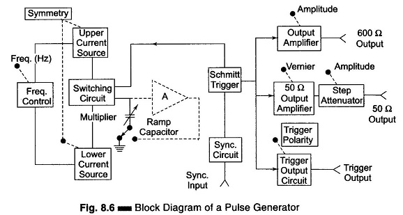
The frequency range of the instrument is covered in seven decade steps from 1 Hz to 10 MHz, with a linearly calibrated dial for continuous adjustment on all ranges.
The duty cycle can be varied from 25 – 75%. Two independent outputs are available, a 50 Q source that supplies pulses with a rise and fall time of 5 ns at 5 V peak amplitude and a 600 Q source which supplies pulses with a rise and fall time of 70 ns at 30 V peak amplitude. The instrument can be operated as a free-running generator, or it can be synchronized with external signals.
The basic generating loop consists of the current sources, the ramp capacitor, the Schmitt trigger and the current switching circuit, as shown in Fig. 8.7.
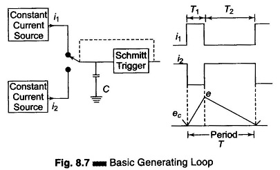
The upper current source supplies a constant current to the capacitor and the capacitor voltage increases linearly. When the positive slope of the ramp voltage reaches the upper limit set by the internal circuit components, the Schmitt trigger changes state. The trigger circuit output becomes negative and reverses the condition of the current switch. The capacitor discharges linearly, controlled by the lower current source. When the negative ramp reaches a predetermined lower level, the Schmitt trigger switches back to its original state. The entire process is then repeated. The ratio i1/i2 determines the duty cycle, and is controlled by symmetry control. The sum of i1 and i2 determines the frequency. The size of the capacitor is selected by the multiplier switch.
The unit is powered by an internal supply that provides regulated voltages for all stages of the instrument.