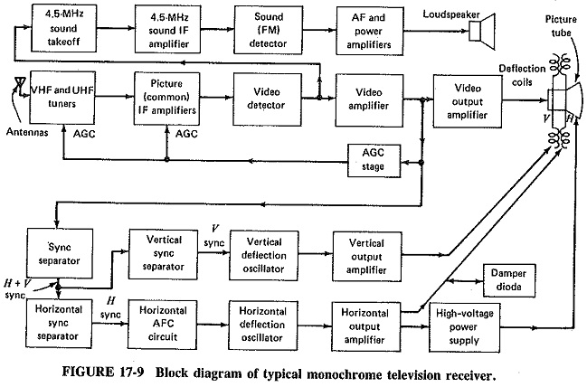
Monochrome Television Receiver Block Diagram:
Monochrome Television Receiver Block Diagram as shown in Figure 17-9, TV receivers use the superheterodyne principle. There is extensive pulse circuitry, to ensure that the demodulated video is displayed correctly. To that extent the TV receiver is quite similar to a radar receiver, but radar scan is generally simpler, nor are sound and color normally required for radar It is also worth making the general comment that TV receivers of current manufacture are likely to be either solid-state or hybrid. In the latter case, all stages are transistor or integrated-circuit, except for the high-power scanning (and possibly video) output stages. It is now proposed to discuss briefly those stages which television receivers have in common with those types of Monochrome Television Receiver Block Diagram, and then to concentrate on the stages that are peculiar to TV receivers.
Common, Video and Sound Circuits:
Tuners:
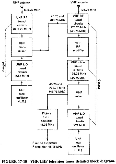
A modern television Monochrome Television Receiver Block Diagram has two tuners. This arrangement was left out of Figure 17-9 for simplification but is shown in detail in figure 17-10.
The VHF tuner must cover the frequency range from 54 to 216 MHz. The antenna most frequently used for reception is the Yagi-Uda, consisting at its simplest of a reflector, a folded dipole for the five lower channels and a shorter dipole for the upper seven channels. More elaborate Yagis may have a reflector, four dipoles and up to six directors.
The frequency range covered by the UHF tuner is the 470- to 890-MHz band, and here the antenna used is quite likely to be a log-periodic, with the one antenna covering the whole band. It is also possible to cover the VHF and UHF bands with the one antenna. This is then likely to be similar to the discone antenna, but with the disk bent out to form a second cone. This biconical antenna is then used for UHF, with wire extensions for the two cones increasing the antenna dimensions for VHF.
VHF tuners often use a turret principle, in which 12 sets of (RF, mixer and local oscillator) coils are mounted in spring-loaded brackets around a central shaft. The turning knob is connected to this shaft, and channels are changed by means of switching in the appropriate set of coils for the fixed tuning capacitor. This automatically means that the tuned circuits for these three stages are ganged together,as shown in Figure 17-10. Fine tuning is achieved by a slight variation of the tuning capacitance in the local oscillator. Most newer-model Monochrome Television Receiver Block Diagram use PLL (phase-locked loop) circuitry to replace switch-type tuners with electronic tuners. Reliability is much better with these tuners, which have no mechanical parts.
The UHF tuner’s active stages are a diode (point-contact or Schottky-barrier) mixer and a bipolar or FET local oscillator. This, like its VHF counterpart, is likely to be a Colpitts oscillator. The diode mixer is used here as the first stage to lower the UHF noise figure adequate gain is available from the remaining RF circuits. Coaxial transmission lines are used instead of coils in the UHF tuner, and they are tuned by means of variable capacitors. These are continuously variable (and of course ganged) over the whole range, but click stops are sometimes provided for the individual channels. Since the IF is quite small compared to the frequency at which the UHF local oscillator operates, AFC is provided. This takes the form of a dc control voltage applied to a varactor diode in the oscillator circuit.
An alternative means of UHF tuning consists of having varactor diodes to which fixed dc increments are applied to change capacitance, instead of variable capacitors. One of the advantages of this arrangement is that it facilitates remote-control channel changing. The remainder of the circuit is unchanged, but a UHF RF amplifier is normally added. The reason for this is the low Q of varactors, necessitating an additional tuned circuit to sharpen up the RF frequency response.
Figure 17-10 shows the VHF channel 7 being received. When any VHF channel is received, the UHF local oscillator is disabled, so that the output of the UHF mixer is a rectified UHF signal (channel 37 in this case), applied to the VHF tuner. This signal is a long way from the VHF radio frequency and has no effect. The significant carriers appearing at the input to the VHF RF amplifier are the picture (P), chroma (C) and sound (S) carriers of channel 7, of which only P is shown in Figure 17-10.
We have P = 175.25 MHz, C = 178.83 MHz and S = 179.75 MHz applied to the RF amplifier, and hence to the mixer. These three are then mixed with the output of the local oscillator operating at the standardised frequency of 45.75 MHz above the picture carrier frequency. The resulting carrier signals fed to the first IF amplifier are P = 45.75 MHz, C = 42.17 MHz and S = 41.25 MHz. The IF bandpass is large enough to accommodate these signals and their accompanying modulating frequencies.
When the VHF tuner is set to the UHF position, the following three things happen:
-
The UHF local oscillator is enabled (dc supply voltage connected).
-
The VHF local oscillator is disabled (dc removed).
-
The VHF tuner RF and mixer tuned circuits are switched to (a picture carrier frequency of) 45.75 MHz.
The UHF tuner is now able to process the channel 37 signal from its antenna. The relevant frequencies, P = 609.25 MHz, C = 612.83 MHz and S = 613.75 MHz, are mixed with the local oscillator frequency of 655 MHz. The resulting outputs from the mixer diode are P = 45.75 MHz, C = 42.17 MHz and S = 41.25 MHz, being of course identical to the IF signals that the VHF tuner producers when receiving channel 7 (or any other channel). These are now fed to the VHF amplifier, which, together with the VHF mixer, acts as an IF amplifier for UHF. It is to be noted that the VHF mixer uses a transistor and not a diode and therefore becomes an amplifier when its local oscillator signal is removed. Since the. UHF tuner has a (conversion) loss instead of a gain, this extra IF amplification is convenient.
The block diagram of Figure 17-10 was drawn in a somewhat unorthodox fashion, tuned circuits being shown separately from the active stages to whose inputs they belong. This is not due to any particular quirk of Monochrome Television Receiver Block Diagram. Rather, it was done to show precisely what circuits are ganged together and to enable all relevant (picture carrier and local oscillator) frequencies to be shown precisely where they occur with either VHF or UHF reception. This means that it was possible to show the sum and difference frequencies at the outputs of the two mixers, with only the difference signals surviving past the next tuned circuit.
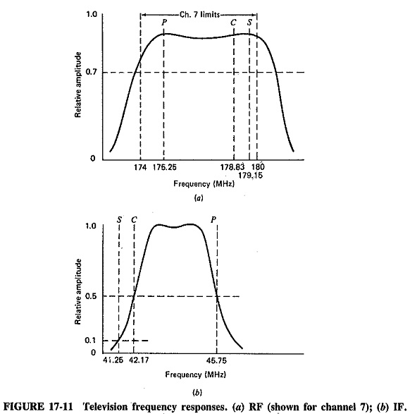
As shown in Figure 17-11, the frequency response of a tuner is quite wide, being similar to, but broader than, the picture IF response. Note that the frequencies in Figure 17-11a apply for channel 7, although those of Figure 17-11b are of course fixed.
Picture IF Amplifiers:
The picture (or common) IF amplifiers are almost invariably double-tuned, because of the high percentage bandwidth required. As in other receivers, the IF amplifiers provide the majority of the sensitivity and gain before demodulation. Three or four stages of amplification are normally used. The IF stages provide amplification for the luminance, chrominance and sound information. As shown in Figure 17-11b, the IF bandwidth is somewhat lower than might be expected, three factors govern this. At the upper end, relative response is down to 50 percent at the picture carrier frequency, to counteract the higher powers available at the lowest video frequencies because of the vestigial sideband modulation used. At the lower end, relative amplitude is also down to 50 percent at the chroma subcarrier frequency, to minimise interference from this signal. At the sound carrier frequency of 41.25 MHz, response is down to about 10 percent, also to reduce interference. If a TV receiver is misaligned or purposely mistuned (with the fine-tuning control), the sound carrier may correspond to a point higher on the IF response curve. If this happens, the extra gain at this frequency will .counteract the subsequent 4.5 MHz filtering, and some of the sound signal will appear in the output of the video amplifiers. This will result in the appearance of distracting horizontal sound bars across the picture, moving in tune with sound frequency changes.
The result of the previous explanations is that the picture IF bandwidth is approximately 3 MHz, as compared with the transmitted video bandwidth of 4.2 MHz. There is a consequent slight reduction in definition because of this compromise, but interference from the other two carriers in the channel is reduced, as is interference from adjacent channels. As anyone who has watched a good TV receiver will know, the resulting picture is perfectly acceptable.
Video Stages:
It will be seen that the last picture IF amplifier is followed by the video detector and (customarily) two video amplifiers, hose output drives the (cathode of the) picture tube. At various points in this sequence, signals are taken off for sound IF, AGC and sync separation. The circuit of Figure 17-12 shows these arrangements in detail.
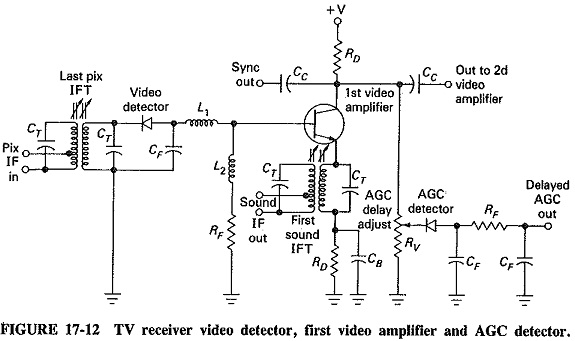
The circuit has a lot in common with detector-AGC circuits described previously. Only the differences will be mentioned here. The first of these is the presence of coils L1 and L2. They are, respectively, series and shunt peaking coils, needed to ensure an adequate frequency response for the video amplifier shown. The second video amplifier also uses such an arrangement. Note that all CT capacitors in Figure 17-12 are fixed running capacitors, with values of a few picofarads. The coils are adjustable for alignment. All components with F subscripts are used for (in this case, low-pass) filtering.
The transformer in the emitter of the first video amplifier, tuned to 4.5 MHz, has two functions. The more obvious of these is to provide the sound IF takeoff point. Since the video detector is a nonlinear resistance, the FM sound signal beats with the picture carrier, to produce the wanted 4.5-MHz frequency difference. This is extracted across the 4.5-MHz tuned transformer and applied to the first sound IF amplifier. At 4.5 MHz, this tuned circuit represents a very high unbypassed emitter impedance, much higher than the load resistance RD. The first video amplifier has a very low gain at the sound intermediate frequency. In fact, this is the second function of this arrangement. The sound IF transformer acts as a trap, to attenuate 4.5-MHz signals in the video output, preventing the appearance of the previously mentioned sound bars. Note finally that a portion of the video output voltage is also taken from here and fed to the sync separator, and another portion is rectified for AGC use. Since the AGC is delayed, a separate diode must be used. Other AGC systems are also in use, including keyed AGC.
The video amplifiers of the TV receiver have an overall frequency response. The second stage drives the picture tube, adjusting the instantaneous voltage between its cathode and grid in proportion to the video voltage. This modulates the beam current and results in the correct degree of whiteness appearing at the correct point of the screen, which is determined by the deflection circuits. The blanking pulses of the composite video signal drive the picture tube beyond cutoff, correctly blanking out the retraces. Although the sync pulses are still present, their only effect is to drive the picture tube even further beyond cutoff. This is quite harmless, so that the removal of the sync pulses from the composite video signal is not warranted.
The contrast and brightness controls are located in the circuitry of the output video amplifier. The contrast control is in fact the direct video equivalent of the volume control in a radio receiver, When contrast is varied, the size of the video output voltage is adjusted, either directly or through a variation in the gain of the video output stage. Note that a typical picture tube requires about 100 V peak to peak of video voltage for good contrast. When an elderly picture tube begins to fade away, it is because it has lost sensitivity, and even maximum contrast is no longer sufficient to drive it fully. The brightness control varies the grid-cathode dc bias on the picture tube, compensating for the average room brightness.
Some receivers perform this function automatically, using a photodiode which is sensitive to ambient brightness, in addition to an adjustable potentiometer. Receivers with a single “picture” control normally have twin potentiometers for brightness and contrast, mounted on the one shaft and therefore adjustable together. This arrangement should not be decried too much. It has the advantage of giving the customer fewer knobs to adjust (i.e., misadjust).
The Sound Section:
As shown in the block diagram of Figure 17-10, the sound section of a television receiver is identical to the corresponding section of an FM receiver. Note that the ratio detector is used for demodulation far more often than not. Note further that the intercarrier system for obtaining the FM sound information is always used, although it is slightly modified in color receivers.