SCR as Half Wave Rectifier Circuit Diagram:
SCRs are very useful in ac circuits where they may serve as rectifiers whose output current can be controlled by controlling the gate current. An example of this type of application is the use of SCRs to operate and control dc motors or dc load from an ac supply. The circuit using an SCR as half wave rectifier is shown in Fig. 26.30 (a). The ac supply to be rectified is applied to the primary of the transformer ensuring that the negative voltage appearing at the secondary of the transformer is less than reverse breakdown voltage of the SCR. The load resistance RL is connected in series with anode. A variable resistance r is inserted in the gate circuit for control of gate current.
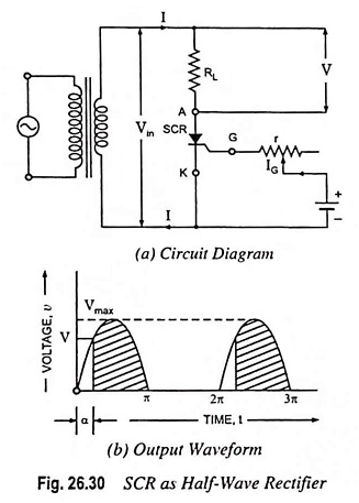
During the -ve half cycles of ac voltage appearing across the secondary, the SCR does not conduct regardless of the gate voltage, because anode is negative w.r.t. cathode and also peak inverse voltage is less than the reverse breakdown voltage. The SCR will conduct during the +ve half cycles provided appropriate gate current is made to flow. The gate current can be varied with the help of variable resistance r inserted in the gate circuit for this purpose. The greater the gate current, the lesser will be the supply voltage at which SCR will start conducting.
Assume that gate current is such that SCR starts conducting at a positive voltage V, being less than peak value of ac voltage, Vmax. From Fig. 26.30 (b) it is clear that SCR will start conducting, as soon as the secondary ac voltage becomes V in the +ve half cycle, and will continue conducting till ac voltage becomes zero when it will turn off. Again in next +ve half cycle, SCR will start conducting when ac secondary voltage becomes V volts.
If the angle at which the SCR starts conducting (i.e., firing angle) is α, the conduction will take place for (π – α) radians.
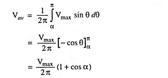
The average output from such a half-wave rectifier connected to a secondary voltage of v = Vmax sin θ is given by an expression
Average output voltage,
Therefore Average current,
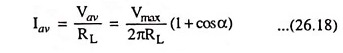
Thus the desired value of average current, Iav can be obtained by varying firing angle α.
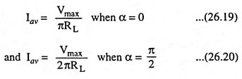
i.e., average current decreases with the increase in value of firing angle α.
The noteworthy point is that in an ordinary half-wave rectifier using a P-N diode, conduction current flows during the whole of the positive cycle whereas in SCR as half wave rectifier the current can be made to flow during the part or full of the positive half cycle by adjustment of gate current. Hence SCR operates as a controlled rectifier and hence the name silicon controlled rectifier.
The output voltage from the SCR rectifier is not a purely dc voltage but also consists of some ac components, called the ripples, along it. The ripple components are undesirable and need to be removed or filtered out.