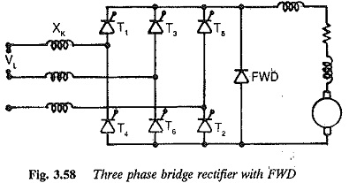
Bridge Rectifier Circuit Diagram with freewheeling diode:
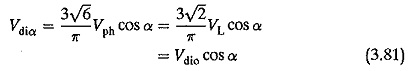
A 6 pulse Bridge Rectifier Circuit Diagram with freewheeling diode across the load terminals is shown in Fig. 3.58. As has already been explained, the diode participates in conduction only when the instantaneous load voltage tends to become negative. This occurs for firing angles greater than 60°. For α ≤ 60° the bridge operates as a fully controlled one and the mean output voltage is
For α > 60° and < 120° the free wheeling action of the diode does not permit negative excursions of the instantaneous voltage and hence the average value of voltage is
![]()
The control characteristic is shown in Fig. 3.60. There is a distinct difference between the output voltage of a half controlled converter and that of a fully controlled one with FWD. But for this difference, the improvement in the power factor, reactive power requirement, etc during free wheeling are the same. These advantages are present only during the free wheeling action.
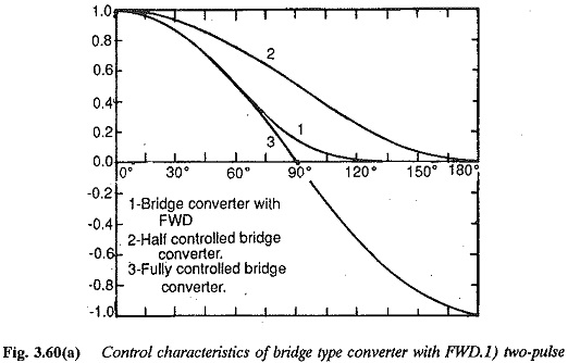
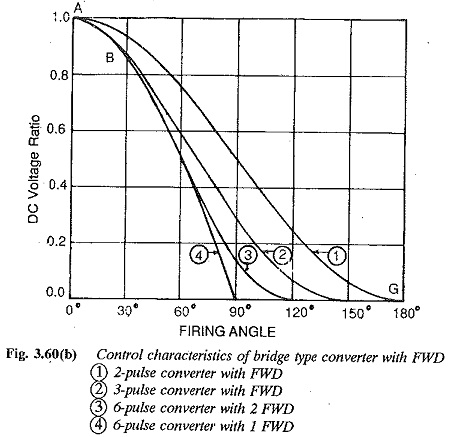
It is clear from the above discussion that as the number of pulses increases, the advantages of FWD get sharply reduced. For example, in a six pulse converter, with a view to saving reactive power, FWD is effective only after α = 60°. On the other hand, in two pulse converters it is effective in the complete range of firing angles, from 0 to 180°. The control reactive power is reduced but not the commutation reactive power. The dc side voltage harmonics are smoothened, thereby reducing the amount of smoothing equipment. The ripple content of the unsmoothed dc voltage is reduced and a continuous dc is available with small smoothing inductances, thereby avoiding discontinuous conduction.
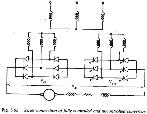
Series connection of converters—one in the fully controlled mode and the other in the uncontrolled mode
The converter connections are shown in Fig. 3.61. Operation is similar to that of a half controlled Bridge Rectifier Circuit Diagram. Actually the principle of a half controlled bridge circuit is extended to obtain the present circuit, by connecting two individual bridge circuits in series, one in the fully controlled mode and the other in the uncontrolled mode. This connection is preferred when high dc voltages are required. The output voltage
![]()
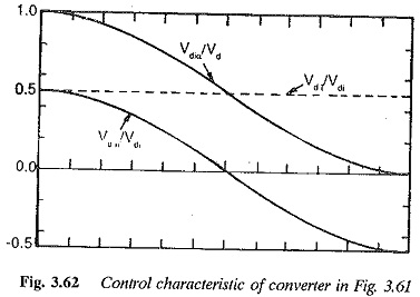
Vdio/2 the output voltage provided by the diode bridge and Vdio/2 cos α is the voltage provided by the thyristor bridge. Also![]()
The control characteristic is shown in Fig. 3.62. Voltage variation up to zero is not possible, due to the inverter limit of the controlled converter. Zero voltage can be obtained by supplying the two converters with different voltages, the supply voltage to the controlled one being 10% greater. The inverter limit is fixed so that there is a margin angle of quenching of 10°.
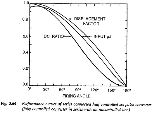
The converter provides some saving in reactive power. The output voltage has a reduced ripple. The voltage and current waveforms are showd in Fig. 3.63. The fundamental displacement factor as seen from the waveforms on the input side is cos(α/2), i.e.
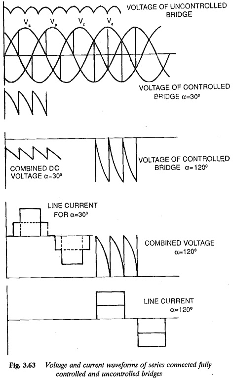
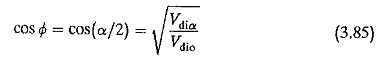
The input harmonics depend upon the firing angle. Therefore the improvement in the total power factor is not quite the same as that in the displacement factor. The total power factor as a function of firing angle is shown in Fig. 3.64.