SCR as Full Wave Rectifier Circuit Diagram:
For Two SCR as Full Wave Rectifier are connected across the centre taped secondary, as shown in Fig. 26.32 (a). The gates of both SCRs are supplied from two gate control supply circuits. One SCR conducts during the + ve half cycle and the other during the -ve half cycle and thus unidirectional current flows in the load circuit.
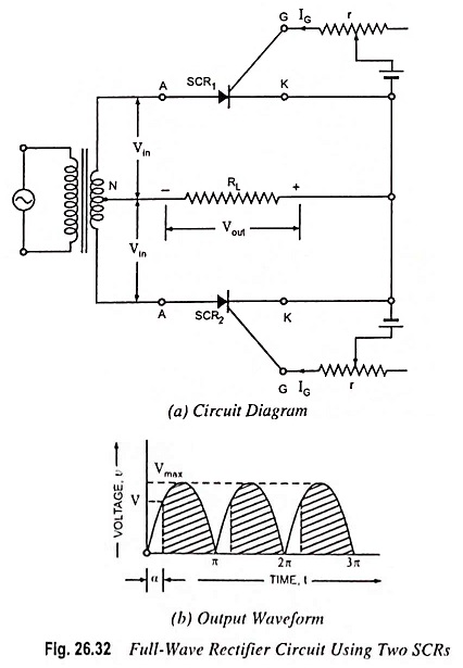
The main advantage of this circuit over ordinary full-wave rectifier circuit is that the output voltage can be controlled by adjusting the gate current.
Now if the supply voltage v = Vmax sin θ and the firing angle is α, then average voltage output will be given by the expression
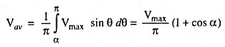
i.e., average voltage output of full-wave rectifier circuit is double of that of half-wave rectifier circuit, which is obvious.
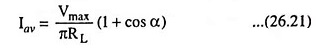
So average current,