Light Activated SCR (LASCR) – Symbol, Construction and Operation:
Light activated SCR is just an ordinary SCR except that it can also be light triggered. Most LASCRs also have a gate terminal for being triggered by an electrical pulse just as a conventional SCR.
Construction:
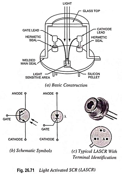
The basic construction of an Light Activated SCR (LASCR) is shown in Fig. 26.71 (a). The schematic symbols most commonly used for the LASCR are shown in Fig. 26.71 (b). The terminal identification and a typical LASCR are shown in Fig. 26.71 (c).
Operations:
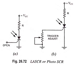
Some LASCRs have clear windows in their cases so that light sources from other devices can be coupled to them. Many have the light source encapsulated in the same package so that a relay is formed. When the light falling on depletion layers is strong enough, valence electrons are dislodged from their orbits and become free electrons. When these free electrons flow out of the collector of one transistor into the base of the other, the positive feedback starts and the LASCR turns on just like a normal SCR, the LASCR will continue to conduct even if the light source is removed. For maximum sensitivity to light, the gate is left open, as shown in Fig. 26.72 (a). Trigger adjust can be included if an adjustable trip point is desired as shown in Fig. 26.72 (b). The gate resistor diverts some of the light produced electrons and alters the sensitivity of the circuit to the incoming light. The devices are for low power applications.
Applications of Light Activated SCR (LASCR):
The LASCRs find many applications including optical light controls, relays, phase control, motor control and a large number of computer applications.
The maximum current (rms) and power (gate) ratings for LASCRs commercially available are about 3 A and 0.1 W. With the increase in junction temperature the light energy required to activate the device is reduced.
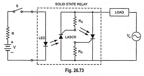
A solid-state relay using two LASCRs in reverse parallel is shown in Fig. 26.73. Two LASCRs are connected in reverse parallel so as to obtain conduction in both half cycles of the applied supply voltage Vs. A single light-emitting diode (LED) is employed for triggering both LASCRs. Bias resistors are used to control the light sensitivity of the gates and avoid sporadic triggering during off periods. Usually all the three active devices (two LASCRs and one LED) and the two bias resistors RG are encapsulated in the same package. Since the relay action does not require direct electrical connection, such relays are often used to couple signals into very high voltage equipment and other dangerous locations.