What is a thermistor? – Definition, Symbol and V-I Characteristics:
The word thermistor is a combination of thermal and resistor. A thermistor is a resistor with definite thermal characteristics. Most thermistors have a negative temperature coefficient, but positive temperature coefficient devices are also available. The reason of negative temperature coefficient of resistance of a semiconductor is that when its temperature is increased, the concentration of charge carriers increases resulting in a decrease in resistance.
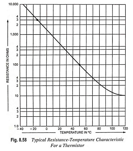
Thermistors are essentially semiconductor devices, that behave as resistors with high negative temperature coefficient (usually – 0.04 per °C at room temperature of 25°C). Thermistor has a very nonlinear resistance-temperature relation, as obvious from the characteristic curve shown in Fig. 8.58. The resistance R of a thermistor at a temperature T can be given by the equation
![]()
where α and β are constants depending upon the material and manufacturing techniques employed.
The approximate relationship between resistance and temperature, applying to most thermistors, can be obtained by rewriting above Eq. (8.25) for temperatures T1 and T0
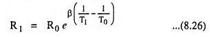
where R1 and R0 are the resistances in ohms at absolute temperatures T1 and T0 respectively, and β is a thermistor constant. β is expressed in Kelvins and is of the order of 4,000. The reference temperature T0 is usually taken as 298 K (or 25°C). β is assumed to be constant for all practical purposes but has generally rising tendency with temperature. The assumption that β is constant gives relationship for the resistance temperature coefficient, given as
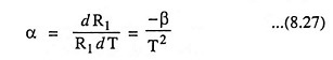
From Eq. (8.27) it is evident that α is not constant but drops with rise in temperature.
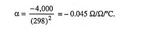
If β = 4,000 and T = 25°C or 298 K, then temperature coefficient of resistance,
The commonly used symbol for the device is given in Fig. 8.59.
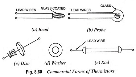
Silicon and germanium are not normally used for manufacturing thermistors, because larger and more predictable temerature coefficients are available with metal oxides. Modern thermistors are manufactured from the oxides of metals like manganese, nickel, cobalt, copper, iron, zinc, aluminium, titanium, magnesium and uranium. These oxides or their sulphides and silicates are milled, mixed in appropriate proportion, pressed into desired shape with appropriate binders, and finally sintered. The electrical terminals are embedded before sintering or baked afterwards. The resistance of the thermistors at room temperature of 25°C varies over a wide range, from several hundred ohms to megaohms. Because of their high resistance they can be manufactured in very small sizes in the form of beads, discs and rods. These are available in a wide variety of shapes and sizes and commercial forms are shown in Fig. 8.60.
V-I Characteristics:
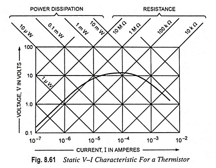
A typical thermistor resistance temperature characteristic is shown in Fig. 8.58. From the curve it is seen that the device resistance decreases by approximately 500 times when heated through 150°C. Current through a thermistor causes power dissipation which raises the temperature of the device. Thus, the device resistance is dependent upon ambient temperature and self-heating. For a fixed ambient temperature, the resistor of a thermistor depends upon its power dissipation. Very small currents have no effect, so that a plot of voltage versus current (Fig. 8.61) shows the device behaving initially as a constant-value resistance. As the current increases, a peak is reached at which the heating effect of the current begins to significantly change the thermal resistance and consequently produces a reduction in voltage across the device.
Thermistors are widely used for temperature compensation i.e., for cancelling the effect of temperature on other electronic devices. They are also used for measurement and control of temperature, liquid level, gas flow etc.
Remarks on Use of Negative Temperature Coefficient (NTC) Thermistors: Do not use unprotected thermistors in conducting fluids or aggressive and reducing gases which may cause a change in thermistor characteristics.
For temperature measurements do not use too high a voltage on the NTC thermistor as self heating may cause incorrect readings.
Positive Temperature Coefficient (PTC) Thermistors: Such thermistors are resistors with a high positive temperature coefficient of resistance. They differ from NTC thermistors in the following aspects.
- The temperature coefficient of a PTC thermistor is positive only between a certain temperature range, outside this range the temperature coefficient is either zero or negative.
- The absolute value of the temperature coefficient of PTC thermistors is usually much higher than that of NTC thermistors.
PTC thermistors are employed as current limiters, temperature sensors, and protectors against overheating in equipment such as electric motors. They are also employed as level indicators, time delay devices, thermostats, compensation resistors etc.
PTC thermistors are prepared from BaTiO3 and SrTiO3 in a similar way as NTC thermistors. If prepared in the absence of oxygen, these semiconductors have a weak negative temperature coefficient. A strong positive temperature coefficient is obtained by firing the samples in an oxygen-rich atmosphere. This is caused by the penetration of oxygen along pores and crystal boundaries during cooling after the firing process. The oxygen atoms, absorbed on the crystal surface attract electrons from a thin zone of the semiconducting crystals. In this way electrical potential barriers are formed consisting of a negative surface charge with, on both sides, thin layers having a positive space charge resulting from the now uncompensated foreign ions. These barriers cause an extra resistance of the thermistor. At very high temperatures, i.e., above 160°C to 200°C the electrons captured at the boundaries are gradually liberated causing the potential barriers to decrease in strength. This means that the PTC loses its properties and may eventually act as an NTC if the temperature becomes too thigh. Therefore the applications of PTC thermistors are restricted by a certain temperature limit.
Remarks on Use of PTC Thermistors:
- Do not apply a voltage above Vmax to the PTC since it may destroy the thermistor.
- Do not connect PTC thermistors in series in order to obtain high voltages or wattages; this may cause one PTC to heat up faster than the other(s) resulting in too high a voltage across this particular PTC.