Tuned Base Oscillator – Definition and Working Principle:
When a parallel tuned L-C circuit is placed in the base-to-ground circuit, the oscillator is known as the tuned base oscillator. The basic circuit of a tuned base oscillator is shown in Fig. 21.11.
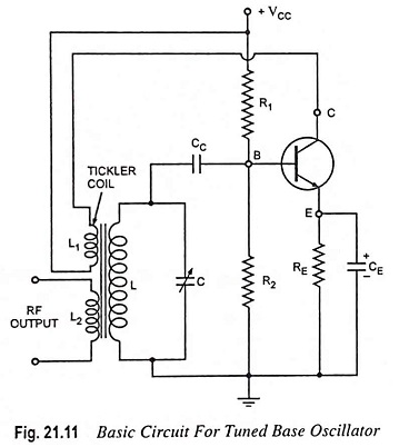
The tuned base oscillator circuit is also named as the tickler oscillator or Armstrong oscillator (named after its inventor). The dc bias is determined by the resistors R1, R2 and RE. The parallel RE-CE network in the emitter circuit is a stabilizing circuit and prevents the degeneration of the signal. As usual, CC is the dc blocking capacitor. L1 and L are the primary and secondary mutually coupled coils of an RF transformer and provide the required feedback between the collector and base circuits. The primary coil L1 is sometimes called a tickler coil.
The amount of feedback depends on the coefficient of coupling between the two coils. Transistor being connected in CE configuration itself provides a phase shift of 180° between its input and output circuits. Another phase shift of 180° is provided by the transformer. Thus a total phase shift of 360° is produced which is an essential condition for developing oscillations. The parallel tuned L-C circuit connected between the base and emitter determines the frequency of oscillation. The tuned L-C circuit resonates at the frequency f0 = 1/2π√LC.
Working Principle:
When the supply VCC is is switched on, the collector current starts increasing. The rising collector current, which also flows through the tickler coil L1, creates a varying magnetic field around L1. This varying magnetic field links with the coil L and, therefore, induces a voltage in the tuned circuit. Because of correct phasing of the coils, and sufficient gain of amplifier, the oscillations start building up.
Dynamic self bias is provided from the R2 – CC combination due to flow of base current. The voltage developed across the capacitor C due to its charging, drives the transistor towards cutoff. This reduces the gain of the transistor amplifier, satisfying the conditions Aβ = 1. Thus sustained oscillations are obtained. The output can be obtained by means of a third coil L2 magnetically coupled to coil L. It has approximately the same waveform as the collector current.
The main drawback of this tuned base oscillator circuit is that the tank circuit gets loaded due to the low base-emitter resistance that comes in shunt with the tuned circuit. This reduces the Q of the tuned circuit and thus the frequency of oscillation differs slightly from the frequency of resonance of the tuned circuit. Because of this reason, the tuned or oscillatory circuit is connected in the collector circuit rather than in base circuit.
However, in case of a vacuum triode or an FET, the input impedance is quite large and, therefore, the tank circuit is not loaded by the input impedance if vacuum triode or FET is employed as an amplifying device. In practice Armstrong oscillator circuits make use of either FETs or vacuum tubes.