OTA Based Ground Inductor and Floating Inductor:
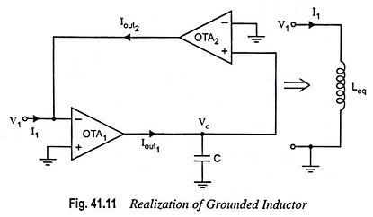
The OTA Based ground inductor can be realized by using 2 OTAs as shown in Fig. 41.11.
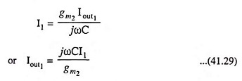
Using Eq. (41.1), we have
![]()
and
![]()
Also we have
![]()
where Vc is the voltage across capacitor and is given as

Substituting Vc = I1/gm2 from Eq. (41.28), we have
From Eqs. (41.26) and (41.29), we have
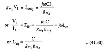
Hence grounded Leq is realized.
The floating inductor can be realized by using 3 OTAs as shown in Fig. 41.12.
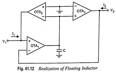
From circuit shown in Fig. 41.12
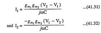
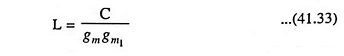
if gm2 = gm3 = gm, then
I2 = -I1, and the floating inductor realized ideally is
However, the parasitic resistors and capacitors can seriously influence the floating inductor realized. Unwanted resistance and capacitance will exist across both ports, the inductor itself will be lossy, the value of inductor will be changed from its ideal value, and a current source will be included in the overall equivalent circuit of the inductor. Whether these departures from ideal behavior will prevent the OTA realization from being utilized depends on the particular application.