Microprocessor Based Firing Circuit of a Thyristor:
Figure 10.64 shows the circuit diagram for Microprocessor Based Firing Circuit of a Thyristor. In a Microprocessor Based Firing Circuit of a Thyristor, it is necessary to synchronize the microprocessor software with the ac input voltage. For this purpose, a zero crossing detector is necessary. A potential transformer is used to reduce the ac supply voltage into 5 V ac and is also used to isolate the power circuit and control circuit. The output voltage of PT is applied to ZCD.
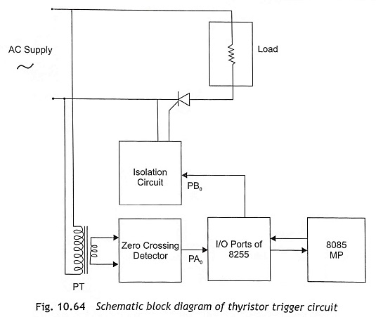
Figure 10.65 shows the ZCD circuit, which generates a pulse on positive zero crossing as well as negative zero crossing of supply voltage.
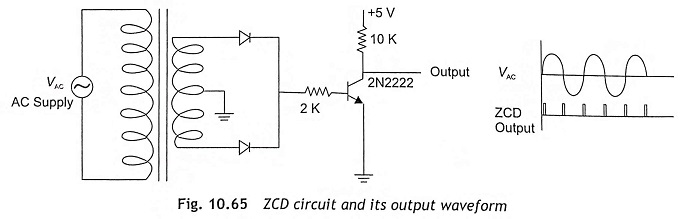
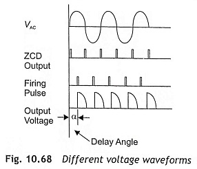
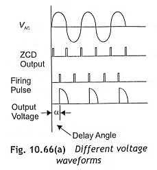
The microprocessor reads the output of ZCD through an input port and detects the zero crossing at the rising edge of the ac voltage waveform. After that, the microprocessor executes a time delay loop and subsequently, it generates the trigger or firing pulse holding it for small time interval. As the output trigger or firing pulse has low power capacity, it cannot be used to trigger the thyristor directly. For that reason, an opto-isolator circuit using MCT2E has been connected to the microprocessor output port and the output of MCT2E is applied to gate-cathode terminals of the thyristor. As the thyristor is forward biased and gate pulse is applied, the thyristor becomes ON and current flows through the load. The ac input voltage, ZCD output, firing pulse and output voltage waveform for a delay angle α are shown in Fig 10.66(a). Again, the microprocessor examines the ZCD output and detects the next rising edge at zero crossing of the ac waveform. After following the time delay, the microprocessor generates the next trigger pulse. Consequently, the above operation will be repeated in cyclic order. The program flow chart for generating firing pulse to turn on a thyristor is depicted in Fig. 10.66(b).
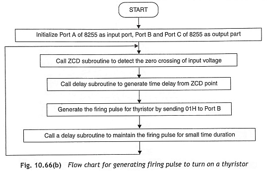
The following steps are used to develop the assembly-language program for Microprocessor Based Firing Circuit of a Thyristor.
Step 1 Initialize all ports A, B and C.
Step 2 Call ZCD subroutine to find the positive zero crossing of ac input voltage.
Step 3 Load HL register pair or any register with 16-bit or 8-bit data respectively and call delay subroutine for creating delay.
Step 4 After delay generation, one pin PB0 will be high. This high output should be maintained for a certain duration. For this, another delay loop will be called.
Step 5 Load any register with 8-bit data and the delay subroutine will be executed for creating delay.
Step 6 After completion of delay, send logic ‘0’ signal at PB0 and then PB0 will be low.
Step 7 Jump to Step 2 to find the next ZCD point and repeat the above process continuously.
This firing circuit can be used for a half-wave rectifier, full-wave rectifier, and ac voltage controller.
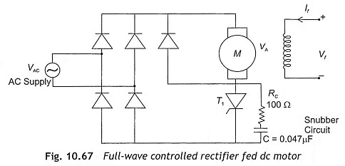
Figure 10.67 shows a bridge-rectifier fed dc motor, which consists of five diodes and one thyristor. The triggering pulses of the thyristor can be controlled by the microprocessor. The assembly-language program for triggering a thyristor, which is already given in this section, can be used for bridge-rectifier-fed dc motor control. Initially, the stack pointer should be defined and initializes Port A as input and ports B and C as output ports. Zero-cross detectors are used to sense the positive going zero and negative going zero of the ac supply voltage. The microprocessor can sense the zero-instant of the ac supply voltage and generates a trigger pulse after a certain delay. The trigger signal from the microprocessor is applied to the input of the optocoupler circuit through PB0 and this trigger pulse must be hold for a certain time interval. The opto-coupler output signal is applied to the gate of the thyristor to make the thyristor ON. Once the thyristor becomes ON, it will be ON for the +ve half cycle of supply voltage. As the rectified dc voltage is fed to the dc motor, the thyristor will also be ON in the -ve half cycle of supply voltage when microprocessor sends the trigger pulse with the same delay in negative half cycle of supply voltage. The ac input voltage, ZCD output, firing pulse and output voltage waveforms are shown in Fig. 10.68.