What is Dual Power Supply? -Circuit Diagram and its Workings?
Many discrete and ICs need bipolar (dual power supply or ± V) supplies. This can be easily accomplished with two three-terminal regulators, as illustrated in Fig. 43.39. Opposite-phase ac is provided by the transformer’s secondary and a grounded center tap. The single full-wave bridge converts these into +ve and -ve dc voltages (with respect to the grounded center tap). Filtering (with respect to ground) is provided by capacitors C1 and C2.
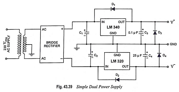
The LM340 provides regulation of the positive voltage, while the LM320 regulates the negative voltage. It is very important to mention here that LM320 has a different pin configuration than the LM340. The case of the LM320 is not ground. So care is to be taken while mounting the negative regulator.
The diodes provide protection, but ensure that they are not reversed. Diodes D1 and D2 ensure that transients on the regulator outputs do not drive the outputs to a potential above their inputs and cause a damage to the regulators. Also, the two regulators may not turn on simultaneously. If this occurs, the output of the slower regulator may be driven toward the potential of the faster one. Diodes D3 and D4 prevent these reverse polarities on start up.
Many applications require several different voltage dual power supply. One solution is to build several independent regulators. However, very often it is important that all of these supply voltages track. That is, if one of the supply voltages goes up 2%, it is best if all of the supply voltages go up by the same amount. It can be accomplished by adding an op-amp to the adjustable three-terminal voltage regulator.
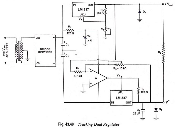
The circuit shown in Fig. 43.40 provides current limiting and thermal shutdown for the negative as well as the positive output voltage. The positive regulated voltage is produced with a LM317 adjustable positive regulator IC, as it was in Fig. 43.40.
The regulated positive voltage is always 1.2 V more positive than the voltage across R3 (on the adjust pin). This regulated output voltage is used as the input of an inverting amplifier. The op-amp A is the input stage of this amplifier, and the LM 337 negative voltage regulator is the power output stage. Consequently, the negative regulated output voltage V– is an amplified and inverted version of the positive regulated voltage V+.
Current limiting and thermal shutdown are independently provided by the LM 317 (for the +ve output) and the LM 337 (for the -ve output). The op-amp assures that the negative output voltage tracks the positive output by driving the LM 337’s adjust pin to +1.2 V above the required negative output. Since the LM 337 is inside the op-amp’s negative feedback loop, this +1.2 V offset appears between the op-amp and the regulator, not at the regulator output.