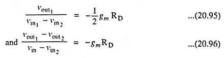
JFET Differential Amplifier – Circuit Diagram and its Workings:
Many differential amplifiers are constructed with FETs because of the large impedance they present to the input signals—an exceptionally important property in many applications, including operational amplifiers and instrumentation amplifiers. A large voltage gain is also important in such applications. Although the FET does not provide much voltage gain, an FET differential amplifier is usually the first stage in a multistage amplifier whose overall gain is very large. FET differential amplifiers are widely found in linear integrated circuits (LICs), as FETs are easily fabricated in IC form. A JFET differential amplifier is depicted in Fig. 20.58.
The two JEETs operate as common-source amplifiers with their source terminals connected. A constant-current provides bias current. A source-to-ground voltage is produced at the common-source connection by source-follower action.
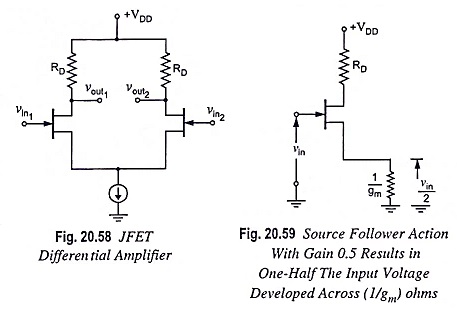
With one input grounded, the output resistance and load resistance of the source follower are both equal to 1/gm (assuming matched devices), so the voltage gain of the source follower is 0.5. So, one-half of the input voltage is produced across 1/gm (Fig. 20.59) and the current is

The output voltage is then
![]()
So

Applying the superposition principle, we find that