Class A Push Pull Amplifier – Working Principle, Advantages & Disadvantages:
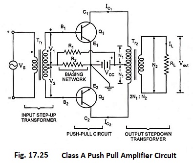
A Class A Push Pull Amplifier circuit is shown in Fig. 17.25. By Class A Push Pull Amplifier means that current flows in the output of the active device (each transistor) for the entire of the input cycle.
Circuit Arrangement:
The circuitry of a typical Class A Push Pull Amplifier is shown in Fig. 17.25. As already mentioned, push-pull amplifier uses two identical transistors, say Q1 and Q2. The emitter terminals of the two transistors Q1 and Q2 connected together. The input signal is applied to the inputs of two transistors through centre tapped step-up transformer Tr1 which provides opposite polarity signals to the two transistor inputs. The collector terminals of both the transistors are connected to end terminals of centre tapped primary of output transformer Tr2. The power supply VCC is connected between the emitter terminals and the centre tap of primary of output transformer. Resistors R1 and R2 are used to provide the proper bias for the circuit. The load RL is connected across the secondary of the output transformer Tr2. The turn ratio (2N1 : N2) of the output transformer is chosen so as to match the load with the output impedance of the amplifier and, therefore, transfer maximum power. The quiescent currents of the two transistors, which are equal in magnitude, flow in opposite directions through each half of primary of the output transformer Tr2, so no saturation of the magnetic core occurs.
Circuit Operation of Class A Push Pull Amplifier:
When the base current of one transistor is being driven positive with respect to the quiescent point Q, the collector current increases, thus causing a decrease in collector potential relative to ground. At the same time, however, a reverse action takes place in the base circuit of the second transistor, i.e., base current
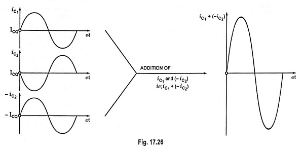
decreases causing a drop in the collector current with a consequent rise in collector potential w.r.t. ground. This means that the ac current flowing through the transformer primary winding is in the same direction. As iC1 increases (i.e., pulls), the current iC2 decreases (i.e., pushes). Hence the name push-pull amplifier. The overall operation results in ac voltage induced in the secondary of the output transformer and thus ac power is delivered to the load. The difference of two collector currents is illustrated in Fig. 17.26.
Distortion:
In view of the fact that the load current in the secondary of the output transformer is proportional to the difference of collector currents, it follows that the harmonic content will be less than it is in either of the collector currents because of cancellation effects. Thus the push-pull arrangement yields much less distortion in the output. This is illustrated below.
The base currents ib1 and ib2 of transistors Q1 and Q2 respectively are expressed as
![]()
Their collector currents are expressed as
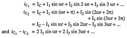
The output voltage induced in the output transformer secondary, being proportional to (iC1 – iC2),

From the above equation for output voltage vout it is obvious that all even harmonics are eliminated. This conclusion was reached on the assumption that the two transistors are identical. If their characteristics differ appreciably, the appearance of even harmonics is not ruled out.
Advantages:
- Because of absence of even harmonics in the output of the push-pull amplifier, such a circuit provides more output per active device for a given amount of distortion or less distortion for a given power output per transistor.
- As already mentioned earlier, the dc components of the collector current oppose each other magnetically in the transformer core. This eliminates any tendency toward core saturation and consequent nonlinear distortion that may arise from the curvature of the transformer magnetization curve.
- Another advantage of this system is that the effects of ripple voltage that may be contained in the power supply because of inadequate filtering will be balanced out. This cancellation results because the currents produced by the ripple voltage are in opposite directions in the transformer winding, and so will not appear in the load. Of course, the power supply hum will also act on the voltage amplifier stages, and so will be part of the input to the power stage. This hum will not be eliminated by the push-pull circuit.
Disadvantages:
The drawbacks of Class A Push Pull Amplifier are
- requirement of two identical or matched pair transistors
- need of use of driver stage to furnish two equal and opposite voltages at the input and
- need of bulky and expensive transformers.