Op Amp Regulators:
The Op Amp Regulators which includes Op-Amp Series Voltage Regulator Circuit, Current Limiting circuit, Foldback Limiting and Op-Amp Shunt Voltage Regulator Circuit. Let us see one by one in detail.
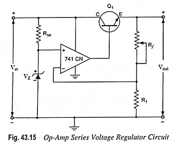
Op-Amp Series Voltage Regulator Circuit:
Op-amp series voltage regulator circuit is shown in Fig. 43.15. The op-amp compares the zener diode reference voltage with the feedback voltage from sensing resistors Rf and R1. If the output voltage varies, the conduction of transistor Q1 is controlled to maintain the output voltage constant. The op-amp places a negligible load on the zener diode, allowing it to operate at a single fixed point. This results in a very stable output from the zener diode. Also, the zener diode no longer must absorb large swings in the current. Hence it can be replaced by a low-power, highly precise reference diode.
The output voltage will be maintained at a value given by the following equation:
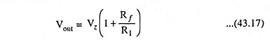
The output voltage can be varied simply by varying Rf in the circuit.
To bias the transistor, the output voltage of the Op Amp Regulators must exceed the circuit’s output voltage Vout by 0.7 V.
![]()
Cautions:
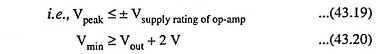
1. The peak value of input voltage (input voltage from the filter) must be kept below the maximum supply voltage for the op-amp (op-amps with rather high supply voltage ratings are available).
2. The voltage from the filter must be at least 2 V above the output voltage Vout. This is essential in order to keep the Op Amp Regulators out of saturation and to keep the zener diode in its breakdown region
The noteworthy point is that the minimum output voltage is Vz, when Rf is shorted. Hence it is necessary that the selected zener diode have a voltage smaller than the lowest desired output voltage.
Finally, making of Rf the potentiometer needs care. Making Rf a potentiometer and running the wiper all the way down to ground will remove all negative feedback. The output voltage will be driven to +Vsat, as the Op Amp Regulators would be operating as a comparator.
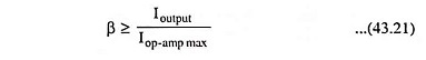
The Op Amp Regulators only has to provide the base current. This is then multiplied by the transistor β to give load current. The transistor β is determined by equation
Also, the transistor must be able to dissipate the power generated:
![]()
where Vdc is the dc output voltage from the filter, Vout is the output (or load) dc voltage and Ioutput is the output (or load) current.
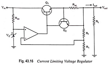
Current Limiting Circuit:
One form of short-circuit or overload protection is current limiting, as illustrated in Fig. 43.16. With the increase in output or load current, the voltage drop across the short-circuit sensing resistor Rsc increases. When the voltage drop across Rsc becomes large enough, it will drive transistor Q2 on, diverting current from the base of transistor Q1, thereby reducing the load current through transistor Q1, preventing any additional current to load resistor RL. The action of components Rsc and Q2 thus provides limiting of the maximum load current.
Foldback Limiting:
Current limiting reduces the output voltage when the output current exceeds the limiting value. The circuit given in Fig. 43.17 provides foldback limiting, which reduces both the output voltage and output current protecting the load from overcurrent, as well as protecting the regulator.
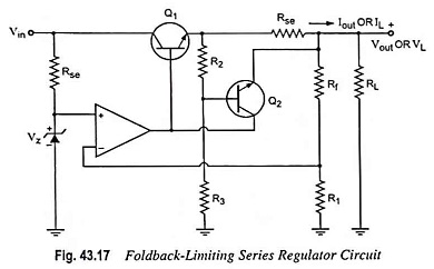
Foldback limiting is provided by additional voltage-divider network of R2 and R3 in the circuit shown in Fig. 43.17 (over that of Fig. 43.16). The divider circuit senses the voltage at the output (emitter) of Q1. With the increase in output current to its maximum value, the voltage across Rse becomes large enough to drive Q2 on, thereby providing current limiting. If the load resistance is made smaller, the voltage driving Q2 on becomes less, so that output current falls when Vout also falls in value—this action being foldback limiting. When the load resistance regains its rated value, the circuit resumes its voltage regulation action.
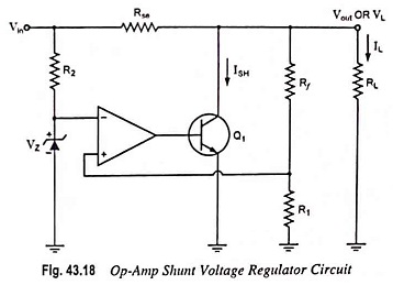
Op-Amp Shunt Voltage Regulator Circuit:
Op-amp shunt voltage regulator circuit is shown in Fig. 43.18. The zener voltage is compared to the feedback voltage obtained from voltage divider network Rf-R1 to provide the control drive current to shunt element Q1. The current through series resistor Rse is thus controlled to drop a voltage across Rse in order to maintain output voltage constant.