Transformer Coupled Transistor Amplifier – Working Principle:
The main cause for low voltage and power gains of an R-C coupled amplifier is that the effective load (Rac) of each stage is reduced due to the low impedance presented by the input of each stage to the preceding stage. This is because the input impedance of an amplifier is low (less than 1 kΩ) while its output impedance is quite high (of the order of 750 kΩ) and when two such amplifiers are coupled to provide a multistage amplifier, the high output impedance of one stage comes in parallel with the low input impedance of subsequent stage and thus effective load is reduced. This drawback has been overcome in a transformer coupled transistor amplifier as by suitably selecting the turn ratio of the transformer, the low resistance of a stage (or load) can be matched with the output impedance of the preceding stage. Transformer coupled transistor amplifier are used when the load is small such as a loudspeaker.
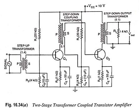
A two-stage transformer coupled amplifier using N-P-N transistors in CE configuration is shown in Fig. 16.34 (a). It is to be noted that step-up transformer is connected to ac signal source so as to increase the voltage level while step-down transformers are used between stages so as to match, as close as possible, the loading of each stage to the output impedance of the preceding stage. This can be achieved by proper selection of turn ratio of the step-down coupling transformers. This is accomplished in an effort to be as close to the maximum power transfer conditions as possible. The coupling transformer is used to feed the output of one stage to the input of the next stage. The collector load is replaced by the primary winding of the coupling transformer. The secondary winding of the coupling transformer replaces the wire between the voltage divider (of the biasing network) and the base of the second stage. A bypass capacitor Cb is used on the bottom of each secondary winding to get an ac ground. This prevents the loss of signal power in the biasing resistors. It should be noted that no coupling capacitor is used in this circuit. The dc isolation between the two stages is provided by the transformer itself. There exists no dc path between the primary and secondary windings of a transformer. However, ac voltage across the primary winding is transferred (with a multiplication factor equal to the turn ratio of the transformer) to the secondary winding. The other components are the same as in an R-C coupled amplifier. In cascaded transistor amplifiers, the input and output impedances of different stages will be different, and therefore, each transformer is required to be designed separately. For excellent performance it is imperative that the transformers are shielded from electrical noise, hum and unwanted pick-ups.
Operation:
When the input ac signal is applied to the base of first transistor through a step-up transformer, it gets amplified and appears across the primary of the coupling transformer. The voltage developed across the primary is transferred to the input of next stage, as shown in Fig. 16.34 (b). The second stage further amplifies in an exactly similar way and so on.
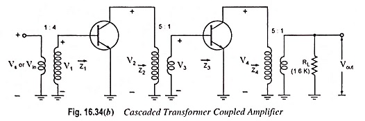
For ac response the circuit given in Fig. 16.34 (a) will appear as shown in Fig. 16.34 (b).
For maximum power transfer, the impedances Z2 and Z4 should be equal to the output impedance of each transistor :
![]()
This is one system where the effect of 1/hoe must be considered.
![]()
Z2 is also 40 kΩ since the input impedance to each stage (Z1 and Z3) is ≡ hie = 1.6 kΩ. Frequency consideration may not always permit Z2 or Z4 to be equal to 1/hoe. For such situations Z2 and Z4 are usually made as close as possible to 1/hoe in magnitude.
For the circuit given in Fig. 16.34 (b)
![]()
and voltage gain for 1st stage,
![]()
Now
![]()
Voltage gain for second stage,
![]()
Output voltage,
![]()
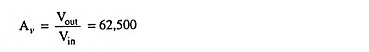
Overall voltage gain,
Frequency Response:
The frequency response of a transformer coupled transistor amplifier is very poor (gain being constant over a small range of frequency), as shown in Fig. 16.35. The output voltage is equal to the collector current multiplied by the leakage reactance of the primary winding. At low frequencies, the primary reactance drops and so the gain is reduced. At high frequencies, the interwinding capacitance acts as a bypass capacitor to reduce the output voltage and hence the gain.
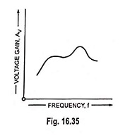
The interwinding capacitance may give rise to a resonance phenomenon at some frequency. This may make the gain of the amplifier very high at this frequency. It follows, therefore, that there will be disproportionate amplification of frequencies in complete signal such as music, speech etc. Hence transformer coupled transistor amplifier introduces frequency distortion. However, it is possible to design a transformer to provide a fairly constant gain over the audio-frequency range but such a transformer may be as costly as 10 to 20 times the R-C coupling.
Advantages:
The main advantage of transformer coupling over R-C coupling is that all the dc voltage supplied by VCC is available at the collector due to absence of collector resistor RC. The operation of this circuit is somewhat more efficient than the R-C coupled transistors due to low dc resistance of the collector circuit of the transformer coupled system. The dc resistance of the primary winding connected in the collector circuit is very low (seldom exceeds a few ohms) in comparison to large collector resistance RC of the R-C coupled system. This lower dc resistance results in a lower dc power loss under the operating conditions and so improves the efficiency of operation.
It provides excellent impedance matching as it is quite simple and convenient to make the inductive reactance of the primary equal to the output impedance of the transistor and inductive reactance of secondary equal to the input impedance of next stage. It provides high gain due to excellent impedance matching.
The coupling is effective when the final output is fed to a low impedance load. For example, the impedance of a typical loudspeaker varies from 4 Ω – 15 Ω whereas the output impedance of a transistor stage is of several hundred ohms. Use of an output transformer can avoid such undesirable effects of such a mismatch.
Disadvantages:
- Poor frequency response, as already explained above.
- Bulky and costly system (transformers being bulky and costlier in comparison to resistors and capacitors), particularly when operated at audio frequencies because of its heavy iron core.
- At radio frequencies, the inductance and interwinding capacitance presents lot of problems.
- Transformer coupling tends to introduce hum in the output.
Applications of Transformer Coupled Transistor Amplifier:
Due to the above drawbacks, transformer coupled transistor amplifier are not used for amplifying low-frequency (audio-frequency) signals. However, they are widely used for amplifying radio-frequency (above 20 kHz) signals. Such amplifiers are mostly used for impedance matching.
Transformer coupled transistor amplifier is generally not used for intermediate stages in a cascaded amplifier because it is costly and bulky. It is used at input or output stage where it can conveniently provide impedance matching.