Magnetic Amplifier – Working Principle and Applications:
In a magnetic amplifier, the basic component is a steel-cored coil with an additional winding energized by direct current. It is intended for controlling alternating current of relatively large power by means of a low power dc.
The simplest practical magnetic amplifier has two identical steel cores with identical ac windings, called the load winding, on each. In addition they have a common dc winding called the control winding. The ac windings are connected together in series or in parallel, and in series with them there is a load. The series connection is used when a short-time response and a high voltage are required, usually in controlling loads requiring low power. The parallel connection, on the other hand, has a slow response of approximate 1 to 3 seconds, but permits control of large current. The control winding is energized by dc.
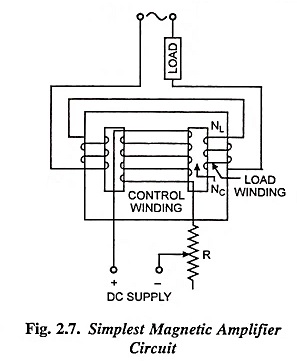
With no current in control winding, the ac winding has a large inductance, and a high reactance is offered to an ac potential. As a result alternating current to the load is limited to a low value by the inductive reactance, and the load voltage is small. When a dc voltage is now applied to control winding the dc magnetic flux passes through the core and the core approaches magnetic saturation, even when a small value of dc voltage is applied. This causes the effective inductance of the ac winding to decrease, so that the ac winding impedance drops. Consequently the alternating current flowing through the ac winding (and the load voltage) increases as the flow of direct current through the control winding increases. Thus, varying the magnitude of control current over a small range causes the load voltage to vary over a wide range.
If a magnetic amplifier consisted only of one core with two windings (ac and control), the load current would be noticeably non-sinusoidal. This is one of the reasons why the simplest practical magnetic amplifier is made double. A second reason is that for one core, the control winding would be linked with an alternating magnetic flux, and an alternating emf would be induced in it. This emf could become very significant for a large value of the ratio NC/NL. With two cores, the total flux linking the control winding does not have an alternating component and, hence, no alternating emf, is induced in it. At present there are a large number of different magnetic amplifier circuits and types of construction.
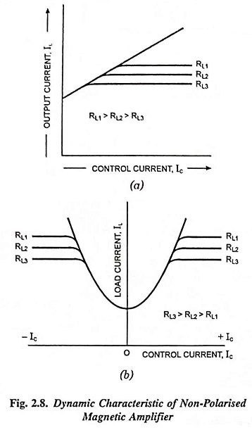
The output or transfer characteristic curves of a magnetic amplifier are shown in Fig. 2.8 for various load resistances. From the curves it is obvious that with the exception of a small region near the origin the load current is directly proportional to the control current up to a value determined by the load resistance, and secondly that the characteristic curve does not begin from the origin but intersects the ordinate axis above the origin. This is due to the current flowing in ac winding which is determined by the applied voltage and the inductive reactance of the winding. Thus for zero control current, load current, IL will be equal to E/XL, known as quiescent current.
Magnetic amplifiers have got following advantages over electronic ones :
- Mechanically sturdy and inherently shockproof.
- Relatively inexpensive amplifiers can be designed to have very high gain, with low input power requirements, and to be compact and light in weight.
- It does not have any filament to be heated as is in the case of vacuum tube amplifiers.
- It can be designed for a wide range of input and output impedances and since the control and load circuits are not conductively coupled, they provide somewhat more flexibility than vacuum tube circuits.
Disadvantages:
On the other hand magnetic amplifiers have limited frequency response and produce an output that is a modulated ac carrier. They have a much lower input impedance than vacuum tubes and provide only a finite power gain where as vacuum tube may theoretically at least, give an infinite power gain. Other disadvantage is that magnetic amplifier, in general, is required to be designed specifically for each application, since both the supply voltage and the load impedance critically affect the operation.
Applications of Magnetic Amplifier:
Magnetic amplifiers are used in electrical systems of control, measurement and automatic regulation as power amplifiers (for example for automatic control of ac and dc motors or in smooth regulation of lighting).
The schematic diagram of a magnetic amplifier control circuit for squirrel cage motor starting as a function of voltage is shown in Fig. 2.9.
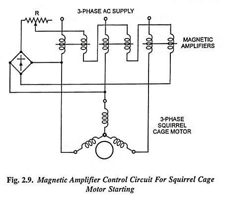
When the ac supply is applied to the motor for starting, the load windings of the magnetic amplifier have a high inductive reactance and only a reduced voltage acts across the stator terminals of the motor. As the motor begins to gain speed, the starting current drops and allows the voltage at the stator terminals to rise. Two of the stator winding terminals are connected to a semiconductor bridge rectifier which serves to excite the control windings of all the three magnetic amplifiers. As the voltage across the stator terminals rises during starting, the direct current through the control windings also rises. As a result, the inductive reactance of the ac windings is reduced and the voltage at the stator terminals rises, The control winding current, due to rise in stator terminal voltage, increases until it finally saturates the amplifiers. By this time the inductive reactance of the ac winding drops practically to zero and the motor operates at full voltage.
The character of motor current and torque change with time during starting may be adjusted by setting up a suitable ratio of the electromagnetic time constant of the magnetic amplifier control winding circuit to the electromechanical time constant of the drive.