Variable Reluctance Stepper Motor Working Principle:
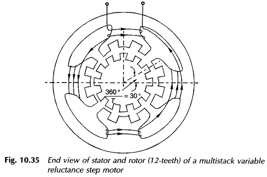
A Variable Reluctance Stepper Motor Working Principle consists of a single or several stacks of stators and rotors-stators have a common frame and rotors have a common shaft as shown in the longitudinal cross-sectional view of Fig. 10.34 for a 3-stack motor. Both stators and rotors have toothed structure as shown in the end view of Fig. 10.35.
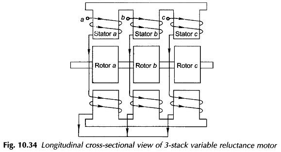
In the Variable Reluctance Stepper Motor Working Principle, the stator and rotor teeth are of same number and size and therefore can be aligned as shown in this figure. The stators are pulse excited, while the rotors are unexcited.
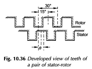
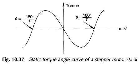
Consider a particular stator and rotor set shown in the developed diagram of Fig. 10.36. As the stator is excited, the rotor is pulled into the nearest minimum reluctance position; the position where stator and rotor teeth are aligned. The static torque acting on the rotor is a function of the angular misalignment θ. There are two positions of zero torque: θ = 0, rotor and stator teeth aligned and θ= 360°/(2 x T) = 180°/T (T= number of rotor teeth), rotor teeth aligned with stator slots. The shape of the static torque-angle curve of one stack of a stepper motor is shown in Fig. 10.37. It is nearly sinusoidal. Teeth aligned position (θ = 0) is a stable position, i.e., slight disturbance from this position in either direction brings the rotor back to it. Tooth-slot aligned position (θ= 180°/T) is unstable i.e, slight disturbance from this position in either direction makes the rotor move away from it. The rotor thus locks into stator in position θ = 0 (or multiple of 360°/T). The dynamic torque-speed characteristic will differ from this due to speed emf induced in stator coils.
While the teeth on all the rotors are perfectly aligned, stator teeth of various stacks differ by an angular displacement of
![]()
where
- n = number of stacks.
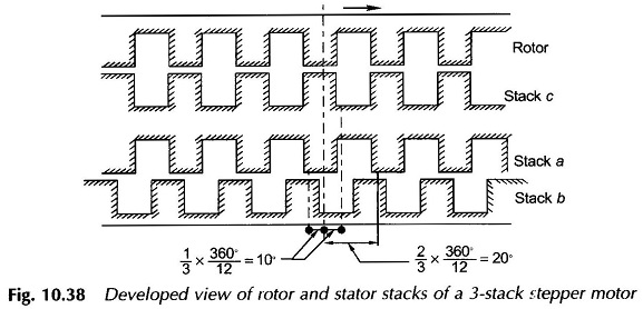
Figure 10.38 shows the developed diagram of a 3-stack stepper motor with rotor in such a position that stack c rotor teeth are aligned with its stator. Here
![]()
In a multiple stack rotor, number of phases equals number of stacks. If phase ‘a’ stator is pulse excited, the rotor will move by 10° in the direction indicated. If instead phase b is excited, the rotor will move by 10° opposite to the direction indicated. Pulse train with sequence abcab will make the rotor go through incremental motion in indicated direction, while sequence bacba will make it move to opposite direction. Directional control is only possible with three or more phases.