Photoemissive cells or Tubes – Working Principle and Types:
These Photoemissive cells or Tubes devices are basically of two types namely vacuum type and gas filled type.
1. Vacuum Type Photocell (or Phototube): This device essentially consists of a thin metal curved sheet with its concave surface coated with Photoemissive cells material forming the cathode and a rod mounted at the centre of the curvature of the cathode forming the plate or anode mounted and enclosed in an evacuated glass envelope as shown in Fig. 25.46. The most important photocathode now used in photocells is the cesium antimony surface, which is characterized by high sensitivity in the visible spectrum. The type of glass employed in the glass envelope determines mainly the sensitivity of the device at other wave lengths. Usually the glass cuts off the transmitted radiations in the ultraviolet region.
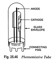
The photocathode emits electrons when stimulated by incident radiant energy and electrons thus emitted are collected by the plate or anode.
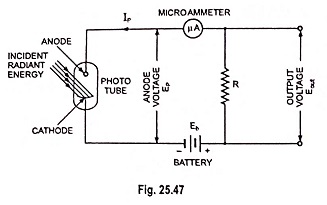
The circuit that can be used for measurement of luminous flux or luminous intensity is shown in Fig. 25.47. The voltage-current characteristics are shown in Fig. 25.48.
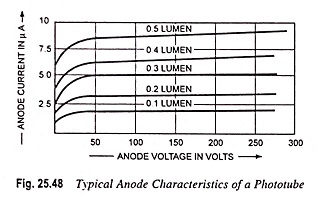
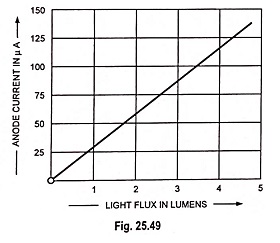
The current through the Photoemissive cells depends upon (i) intensity of light (ii) colour or wavelength of light and (iii) the voltage applied between cathode and plate. From the voltage-ampere characteristics shown in Fig. 25.48 it is obvious that when sufficient voltage is applied between the photocathode and the anode, the plate current entirely depends upon the amount of incident light. Vacuum phototubes are characterized by a photocurrent response that is linear over a wide range so much so that these tubes are frequently used as standards in light comparison measurements. Linear current-light relationship is shown in Fig. 25.49.
The microammeter shown in the circuit diagram may be directly calibrated in terms of luminous flux or luminous intensity. Alternatively a resistor R is connected in the circuit and voltage across the resistor R, Eout, gives the luminous flux or luminous intensity. The output voltage may be amplified for driving the subsequent stages of the measurement system.
The main advantage of such tubes is that these are stable and do not change their characteristics over long periods of time provided these are operated at low voltage and are protected against excessive current. The main drawback of such Photoemissive cells is low sensitivity.
These tubes are used to best advantage in applications requiring the observation of light pulses of short duration, or light modulated at relatively high frequencies.
2. Gas Filled Photocells (or Phototubes): The main drawback of low sensitivity of vacuum type photocells has been overcome to some extent by increasing the number of electrons produced at the cathode by a gas discharge.
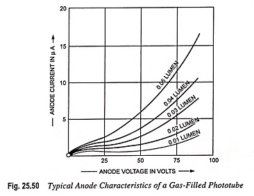
There is no difference in the construction of vacuum type and gas-filled type photocells except that the envelope of the latter contains innert gas, usually argon at a very low pressure (say 1 mm of Hg). Electrons are emitted from the cathode by photoelectric action and accelerate through the gas by the applied voltage at the anode. If the energy of the electrons exceeds the ionization potential of the gas (15.7 V for argon), the collision of an electron and a gas molecule can result in ionization i.e., creation of a + ve ion and a second electron. With the further increase in voltage beyond ionization potential, the anode current increases due to higher number of collisions between photoelectrons and gas molecules. This process may give a gain over the response of a vacuum phototube of about 5-10. If the anode voltage is raised beyond a critical value, which depends upon the tube geometry, gas filling and illumination, the current becomes uncontrolled, all the gas molecules are ionized and the tube exhibits a glow discharge. This condition should be avoided because it may permanently damage the phototube. A resistor should always be connected in series with the gas-filled tube in order to limit the anode current in case of an accidental over-voltage. Typical current-voltage characteristics for various light levels are shown in Fig. 25.50.
The luminous sensitivity of gas-filled phototubes lies between 40 and 150 μA/lumen and radiant sensitivity lies between 0.01 and 0.15 μA/μW.
The drawbacks of gas-filled phototubes are that (i) these are not as stable as vacuum tubes (ii) their characteristics are nonlinear and (iii) they exhibit a time lag in response to modulated or chopped light at frequencies beyond 10 kHz.
These tubes are employed in motion picture industry as sound-on-film sensors.
3. Multiplier Phototubes: It is an extremely sensitive device and is widely used for detecting very low levels of luminous intensity. A photomultiplier tube consists of an evacuated glass envelope containing a photocathode, an anode and several electrodes, known as dynodes. Its principle is illustrated in Fig. 25.51.
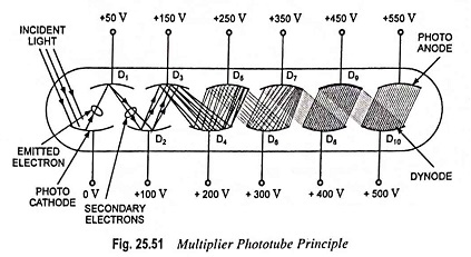
In photomultiplier tube the electrons emitted by the photocathode are electrostatically directed toward a secondary emitting surface, called the dynode. When the proper operating voltage is applied to the dynode, three to six secondary electrons are emitted for every primary electron striking the dynode. These secondary electrons are focused to a second dynode, where the process is repeated. The original emission from the photocathode is thus multiplied many times and, therefore, photo-emission currents of the order of microamperes are converted to more useful milliampere levels. Current amplifications of up to 106 are possible, depending upon the number of dynodes and the properties of material of dynode used.
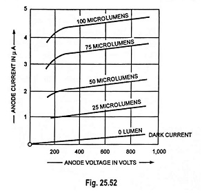
The characteristics of a typical photomultiplier tube are shown in Fig. 25.52. High voltages (500 V to 5,000 V) are required to operate this device. The dark current, which flows when the cathode is not illuminated, results due to thermal emission and the influence of the high voltage electrodes. For incident illumination of a given wavelength, the number of electrons emitted is directly proportional to the illumination intensity. Thus, for a particular illumination the anode current of the photomultiplier tube should tend to remain constant as the anode voltage is increased. However, the dark current always adds to the anode current caused by illumination, and secondary emission improves with increase in applied voltage, consequently, the anode current tends to increase slightly with increase in anode voltage.
The advantages of multiplier phototubes are that (i) these have a high frequency response and high sensitivity (as high as 20 A/lumen as compared to 100 μ A/lumen for photoelectric cells) and their spectral response can be varied from 100 nm to 1,000 nm by changing the cathode material.
The drawback of such tubes is that they are large in size and expensive in cost and require high voltage (between 500 and 5,000 V) for their operation.
These tubes, because of their tremendous amplifying capability, are used extensively in photoelectric measurement and control devices and also as scintillation counters.