Types of Travelling Wave Tubes:
The TWT is the most versatile and most frequently used microwave tube. Four Types of Travelling Wave Tubes, each with particular applications and performance requirements. These are now described.
TWT Types:
The most fruitful method of categorizing traveling-wave tubes seems to be according to size, power levels and type of operation. Within each category, various slow-wave structures and focusing methods may be used.
The first Types of Travelling Wave Tubes were broadband, low-noise, low-level amplifiers used mainly for receivers. That is now a much-diminished application, because transistor amplifiers have much better noise figures, much lower bulk and comparable bandwidths. They are not as radiation-immune as the TWT and not as suitable for hazardous environments. The TWX19, whose performance is given in Table 11-2, is typical of such tubes. It comes all enclosed with its power supply and draws just a few watts from the mains. The package measures about 30 X 5 X 5 cm and weighs about 1 1/2 kg.
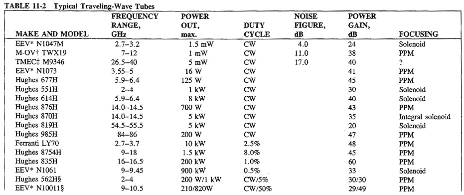
The second Types of Travelling Wave Tubes is the CW power traveling-wave tube. It is represented by several of the entries in Table 11-2 (all those that produce watts or kilowatts of CW). The 677H is typical, weighing just under 2 3/4 kg and measuring 7 X 7 X 41 cm. The major application for this type of TWT is in satellite communications, either in satellite earth stations (types 614H and 870H in Table 11-2) or aboard the satellites themselves (type 677H). This type is also increasingly used in CW radar and electronic countermeasures (ECM); indeed, tubes such as type 819H in Table 11-2 are designed for this application.
Pulsed TWTs are representative of the third category, and several are shown in Table 11-2. They are considerably bigger and more powerful than the preceding two types. A representative tube is the Hughes 797H, illustrated in Figure 11-21. This TWT produces 9 kW in the X band, with a duty cycle of 50 percent. It weighs just over 20 kg, draws 2.5 A at 8 kV dc and measures 53 X 15 X 20 cm.
The fourth Types of Travelling Wave Tubes is the newest, still under active development. It comprises dual-mode TWTs. These are types with military applications, capable of being used as either CW or pulsed amplifiers. They are comparable in size, power, weight and mains requirements to the medium-power communications TWTs. The type 562H tube in Table 11-2 weighs 4.5 kg and is 45 cm long. Although the TWT in general represents a fairly mature technology, the dual-mode tube does not.
Performance:
Low-level, low-noise TWTs are available in the 2- to 40-GHz range, and three are shown in Table 11-2. Such tubes generally use helixes and have octave bandwidths or sometimes even more. Their gains range from 25 to 45 dB and noise figures from 4 to 17 dB, while typical power output is 1 to 100 mW. They tend now to be used mostly for replacement purposes, having been displaced by transistor (FET or bipolar) amplifiers in most new equipment except in specialized applications.
By virtue of their applications, CW power tubes are made essentially in two power ranges up to about 100 W and over about 500 W. Several of them are featured in Table 11-2. The frequency range covered is from under 1 to over 100 GHz, with typically 2 to 15 percent bandwidths. Available output powers exceed 10 kW with gains that may be over 50 kB, and efficiencies are in the 25 to 35 percent range with normal techniques. With a so-called depressed collector efficiencies can exceed 50 percent. This is a system in which the collector potential is made lower than the cathode potential to reduce dissipation and improve efficiency. The tube of Figure 11-21 uses the depressed collector technique. TWTs of this type employ the helix when octave bandwidths are required and the coupled-cavity structure for narrower bandwidths. Focusing is PPM most often, and a noise figure of 30 dB is typical. For space applications, re liabilities of the order of 50,000 hours (nearly 6 years) mean time between failures are now available.
Over the frequency range of approximately 2 to 100 GHz, pulsed TWTs are available with peak outputs from 1 to about 250 kW typically. However, powers in the megawatt range are also possible. Bandwidths range from narrow (5 percent) to three octaves with helix tubes at the lower end of the power range. All manners of focusing and slow-wave structures are employed. Duty cycles can be much higher than for magnetrons or klystrons, 10 percent or higher being not uncommon. All other performance figures are as for CW power TWTs.
Dual-mode Types of Travelling Wave Tubes are currently available for the 2- to 18-GHz spectrum. Power outputs range up to 3 kW pulsed and 600 W CW, with a maximum 10:1 pulse-up ratio (peak pulse power to CW ratio for the same tube), which should be raised even more in the near future. The remaining data are as for single-mode pulsed TWTs, and two dual-mode tubes are shown in Table 11-2.
Applications:
As has been stated, Types of Travelling Wave Tubes are very versatile indeed. The low-power, low-noise ones have been used in radar and other microwave receivers, in laboratory instruments and as drivers for more powerful tubes. Their hold on these applications is much more tenuous than it was, because of semiconductor advances. As will be seen in the next chapter, transistor amplifiers, tunnel diodes and Schottky diodes can handle a lot of this work, while the TWT never could challenge parametric amplifiers and masers for the lowest-noise applications.
Medium- and high-power CW TWTs are used for communications and radar, including ECM. The vast majority of space-borne power output amplifiers ever employed have been TWTs because of the high reliability, high gain, large bandwidths and constant performance in space. The majority of satellite earth stations use TWTs as output tubes, and so do quite a number of tropospheric scatter links. Broadband microwave links also use TWTs, generally employing tubes in the under 100-W range. CW traveling-wave tubes are also used in some kinds of radar, and also in radar jamming, which is a form of ECM. In this application, the TWT is fed from a broadband noise source, and its output is transmitted to confuse enemy radar.
CW tubes will of course handle FM and may be used either to amplify Am signals or to generate them. For AM generation, the modulating signal is fed to the previously mentioned special grid. However, it must be noted that the TWT, like the klystron amplifier, begins to saturate at about 70 percent of maximum output and ceases to be linear thereafter. Although this does not matter when amplifying FM signals, it most certainly does matter when AM signals are being amplified or generated, and in this case the tube cannot be used for power outputs exceeding 70 percent of maximum.
Pulsed tubes find applications in airborne and ship-borne radar, as well as in high-power ground-based radars. They are capable of much higher duty cycles than klystrons or magnetrons and are thus used in applications where this feature is required.