Traveling Wave Tube Working(TWT):
Like the multicavity klystron, the Traveling Wave Tube Working is a linear-beam tube used as a microwave amplifier. Unlike the klystron, however, it is a device in which the interaction between the beam and the RF field is continuous. The TWT was invented independently by Kompfner in Britain and then Pierce in the United States, shortly after World War II, Each of them was dissatisfied with the very brief interaction in the multicavity klystron, and each invented a slow-wave structure in which extended interaction took place. Because of its construction and operating principles, as will be seen, the TWT is capable of enormous bandwidths. Its main application is as a medium- or high-power amplifier, either CW or pulsed.
TWT Fundamentals:
In order to prolong the interaction between an electron beam and an RF field, it is necessary to ensure that both are moving in the same direction with approximately the same velocity. This relation is quite different from the multicavity klystron, in which the electron beam travels but the RF field is stationary. The problem that must be solved is that an RF field travels with the velocity of light, while the electron beam’s velocity is unlikely to exceed 10 percent of that, even with a very high anode voltage. The solution is to retard the RF field with a slow-wave structure. Several such structures are in use, the helix and a waveguide coupled-cavity arrangement being the most common.
Description:
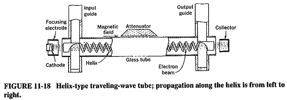
A typical Traveling Wave Tube Working using a helix is shown in Figure 11-18. An electron gun is employed to produce a very narrow electron beam, which is then sent through the center of a long axial helix. The helix is made positive with respect to the cathode, and the collector even more so. Thus the beam is attracted to the collector and acquires a high velocity. It is kept from spreading, as in the multicavity klystron, by a dc axial magnetic field, whose presence is indicated in Figure 11-18 though the magnet itself is not shown. The beam must be narrow and correctly focused, so that it will pass through the center of the helix without touching the helix itself.
Signal is applied to the input end of the helix, via a waveguide as indicated, or through a coaxial line. This field propagates around the helix with a speed that is hardly different from the velocity of light in free space. However, the speed with which the electric field advances axially is equal to the velocity of light multiplied by the ratio of helix pitch to helix circumference. This can be made (relatively) quite slow and approximately equal to the electron beam velocity. The axial RF field and the beam can now interact continuously, with the beam bunching and giving energy to the field. Almost complete bunching is the result, and so is high gain.
Operation:
The Traveling Wave Tube Working may be considered as the limiting case of the multicavity klystron, one that has a very large number of closely spaced gaps, with a phase change that progresses at approximately the velocity of the electron beam. This also means that there is a lot of similarity here to the magnetron, in which much the same process takes place, but around a closed circular path rather than in a straight line.
Bunching takes place in the Traveling Wave Tube Working through a process that is a cross between those of the multicavity klystron and the magnetron.
Electrons leaving the cathode at random quickly encounter the weak axial RF field at the input end of the helix, which–is due to the input signal. As with the passage of electrons across a gap, velocity modulation takes place and with it, between adjacent tums, some bunching. Once again it takes theoretically no power to provide velocity modulation, since there are equal numbers of accelerated and retarded electrons. By the time this initial bunch arrives at the next turn of the helix, the signal there is of such phase as to retard the bunch slightly and also to help the bunching process a little more. Thus, the next bunch to arrive at this point will encounter a somewhat higher RF electric field than would have existed if the first bunch had not made its mark.
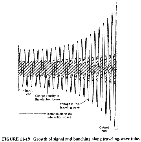
The process continues as the wave and electron beam both travel toward the output end of the helix. Bunching becomes more and more pronounced until it is almost complete at the output end. Simultaneously the RF wave on the helix grows (exponentially, as it happens) and also reaches its maximum at the output end. This situation is shown in Figure 1149.
The interaction between the beam and the RF field is very similar to that of the magnetron. In both devices electrons are made to give some of their energy to the RF field, through being slowed down by the field, and in both devices a phase-focusing mechanism operates. It will be recalled that this tends to ensure that electrons bunch and that the bunches tend to keep arriving in the most favored position for giving up energy. There is at least one significant difference between the devices, and it deals with the methods of keeping the velocity of the beam much the same as that of the RF field, even though electrons in the beam are continually retarded. In the magnetron this is done by the dc magnetic field, but since there is no such field here (no component of it at right angles to the direction of motion of the electrons, at any rate), the axial dc electric field must provide the energy. A method of doing this is to give the electron beam an initial velocity that is slightly greater than that of the axial RF field. The extra initial velocity of electrons in the beam balances the retardation due to energy being given to the RF field.
Practical Considerations:
Among the points to be considered now are the various types of slow-wave structures in use, prevention of oscillations, and focusing methods.
Slow Wave Structures:
Although the helix is a common type of slow-wave structure in use with TWTs, it does have limitations as well as good points. The best of the latter is that it is inherently a nonresonant structure, so that enormous bandwidths can be obtained from tubes using it. On the other hand, the helix turns are in close proximity, and so oscillations caused by feedback may occur at high frequencies. The helix may also be prevented from working at the highest frequencies because its diameter must be reduced with frequency to allow a high RF field at its center. In turn, this presents focusing difficulties, especially under operating conditions where vibration is possible. Care must be taken to prevent high power from being intercepted by the (by now very small-diameter) helix; otherwise the helix tends to melt.
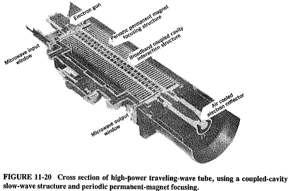
A suitable structure for high-power and/or high-frequency operation is the coupled-cavity circuit, used by the Traveling Wave Tube Working of Figure 11-20. It consists of a large number of coupled (actually, overcoupled) cavities and is reminiscent of a klystron with a very large number of intermediate cavities. It acts as a distributed filter, with a principle of operation that is identical to that of pulse forming networks. Essentially, there is a continuous phase shift progressing along the adjoining cavities. Because these are overcoupled, it may be shown that the system behaves as a bandpass filter. This gives it a good bandwidth in practice but not as good as the exceptional bandwidth provided by helix TWTs. This type of slow-wave structure tends to be limited to frequencies below 100 GHz, above which ring-bar and other structures may be employed.
Prevention of oscillations:
Figure 11-19 shows the exponential signal growth along the traveling-wave tube, but it is not to scale the actual gain could easily exceed 80 dB. Oscillations are thus possible in such a high-gain device, especially if poor load matching causes significant reflections along the slow-wave structure. The problem is aggravated by the very close coupling of the slow-wave circuits. Thus all practical tubes use some form of attenuator (which has the subsidiary effect of somewhat reducing gain). Both forward and reverse waves are attenuated, but the forward wave is able to continue and to grow past the attenuator, because bunching is unaffected. With helix tubes, the attenuator may be a lossy metallic coating (such as aquadag or Kanthal) on the surface of the glass tube. As shown in Figure 11-20, with a coupled-cavity slow-wave structure there are really several (three, in this case) loosely coupled, self-contained structures, between which attenuation takes place. It should be noted that Figure 11-19 shows a simplified picture of signal and bunching growth, corresponding to a TWT without an attenuator.
Focusing:
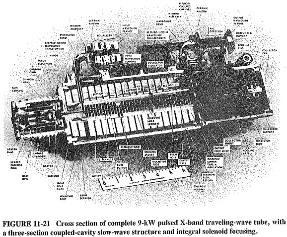
Because of the length of the TWT, focusing by means of a permanent magnet is somewhat awkward, and focusing with an electromagnet is bulky and wasteful of power. On the other hand, the solenoid does provide an excellent focusing magnetic field, so that it is often employed in high-power (ground-based) radars. The latest technique in this field is the integral solenoid, a development that makes the assembly light enough for airborne use. Figure 11-21 shows the cross section of a Traveling Wave Tube Working with this type of focusing.
To reduce bulk, periodic permanent-magnet focusing is very often used. This PPM focusing was mentioned in connection with klystron amplifiers and is now illustrated in Figure 11-20. PPM is seen to be a system in which a series of small magnets are located right along the tube, with spaces between adjoining magnets. The beam defocuses slightly past each pole piece but is refocused by the next magnet. Note that the individual magnets are interconnected. The system illustrated is the so-called radial magnet (as opposed to axial magnet) PPM.