Square Wave Generators:
Diode clippers can be used to remove the curved portion of the sinusoidal wave to give square waves. The operational amplifier together with an integrator, can be used to generate a square wave. The simplest form of the Square Wave Generators is the astable multivibrator shown in Fig. (10.30).
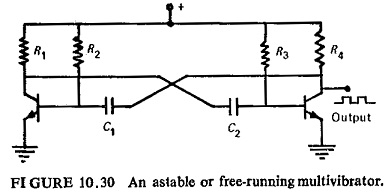
where two junction transistors are cross-coupled. The transistors conduct alternately with very fast regenerative transitions owing to the presence of the cross-coupling capacitors. The circuit is symmetrical if R2=R8,R1=R4 and C1=C2. A rectangular voltage waveform can be obtained across either of the collector load resistors.
Level Detectors:
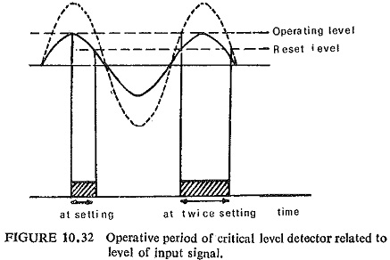
The critical level detector compares an alternating or unsmoothed rectified signal against a d.c. datum, and is intentionally designed to have a low reset ratio. For peak inputs below the datum, the output is zero, but at the critical peak input there is a finite output pulse, the width of which is determined by the reset ratio as illustrated for the half-wave case in Fig. (10.32).
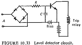
The simplest form of level detector is shown in Fig. (10.33) where the input voltage must exceed the opposing bias voltage before any output is produced.
A practical self-energized circuit using these principles is shown in Fig. (10.34). The full wave unsmoothed input signal feeds two alternative paths I1 and I2. Below the critical level the measuring and switching circuit is fully conducting, so that the current I2 is for all practical purposes zero. The datum Vz, derived from the zener diode Z1, is substantially d.c. at the critical input level. The loading on the input circuit, up to critical level is controlled solely by R3, which provides the voltage for the measuring and switching circuit through R1R2. The critical level occurs when the voltage across R1 exceeds Vz by the small amount of ΔV required to operate the switching circuit, which then switches to a high output impedance and diverts the current I2 into the pulse-integrating circuit.

At the instant of switching the input through R1 increases to a value dependent on the input impedance of the pulse-integrating circuit, relative to R3. This provides positive feedback to the measuring circuit, which controls the instantaneous reset level. The choice of this reset level is a compromise between the extraction of reactive power from the CT and other requirements, such as transient-free properties.