Class D Power Amplifiers – Circuit Diagram, Operation and Applications:
Historically, audio amplifiers have been configured as class A, class B or class AB and the art of design is well known. Also well known is the poor efficiency of these amplifiers compared to that of class D amplifiers. Whereas the theoretical best efficiency for class B amplifiers is 78.5%, the practical upper limit is more nearly 70% when driving a purely resistive load. But when driving real speaker loads which can have power factor angles of 60° or more, efficiency can come down to 55% or less. Class D Power Amplifiers, however, can attain efficiencies of 90%, and with careful component choices can exceed 95% even. Moreover, the power factor of the load does not affect the on-state power losses in the MOSFET switches normally used in such amplifiers. Using class D techniques, amplifiers capable of delivering several hundred watts to the load can be designed using small, inexpensive, stamped heat sinks. Efficiency of class D amplifiers opens the possibility for powerful, small, light amplifiers with good sound quality to be designed today.
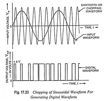
A Class D Power Amplifiers is designed to operate with digital or pulse-type signals. It is necessary, however, to convert any input signal into a pulse-type waveform before using it to drive a large power load and to convert the signal back to a sinusoidal-type signal to recover the original signal. Figure 17.23 illustrates how a sinusoidal signal may be converted into a pulse-type signal using some form of sawtooth or chopping waveform to be applied with the input into a comparator type op-amp circuit so that a representative pulse-type signal is generated. While the letter D is used to describe the next type of bias operation after class C, the D could also be considered to stand for “Digital” since that is the nature of signals provided to the class D amplifier.
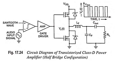
Fig. 17.24 shows a circuit diagram of a transistorized class-D power amplifier required to amplify the digital signal and then convert back to the sinusoidal type signal employing a low-pass filter. It involves a reference sawtooth waveform to be supplied to a comparator along with the input audio signal under amplification. The output of the comparator is a pulse width modulated (PWM) signal which is supplied to the gate driver amplifier to alternatively switch the transistors. Power MOSFET devices have been quite popular as the driver devices for class D power amplifiers. The output at point x is a PWM signal swinging between VDD and ground. This PWM signal is a modulated form of the input audio signal. To convert it back to the audio signal low pass filtering is accomplished by employing high-order low-pass filters. The LF, CF are the low-pass filter components.
The driver should turn on any of the Two MOSFETs at a time, because if both MOSFETs are turned on simultaneously, VDD will get shorted to ground. That is why, two separate signals with certain gap, known as dead time is used for driving the gate of the two MOSFETs. During the dead time, one MOSFET gets enough time to turn-off completely so that the other can be turned on now. Larger dead time reduces the efficiency of operation. MOSFETs in particular have body-diode which acts as a parasitic capacitor and increase switching time. Hence, for reducing the switching time of the transistors Schottky diodes are employed in parallel to the source and drain to faster the switching speed of the transistor. This reduces the dead time which enhances the operation efficiency.
Since the amplifier transistor devices used to provide the output are basically either off or on, they provide current only when they are turned on, with little power loss due to their low on-voltage. As most of the power supplied to the amplifier is transferred to the load, the circuit efficiency is typically very high.
Class D power amplifiers efficiency is largely determined by the ratio of the load resistance to the total dc loop resistance which is the sum of the rDC (ON) of the MOSFETs, wire resistances (including the output filter) and current sense resistor if used, and the load resistance. For highest efficiency, the MOSFET rDC (ON) resistances, shunt and filter resistances should be small compared to the load resistance. In audio class D applications, MOSFETs are employed instead of IGBTs and BJTs because the switching frequencies required to keep distortion low at 20 kHz signal frequencies can exceed 150 kHz and neither the bipolar power transistors or IGBTs switch efficiently at such high frequencies.
Although class A, class AB, and class B, amplifiers are mostly employed as power amplifiers, Class D power amplifiers are popular because of their very high efficiency. Class C amplifiers do find use in tuned circuits as employed in communications.