UJT Relaxation Oscillator – Circuit Diagram and its Workings:
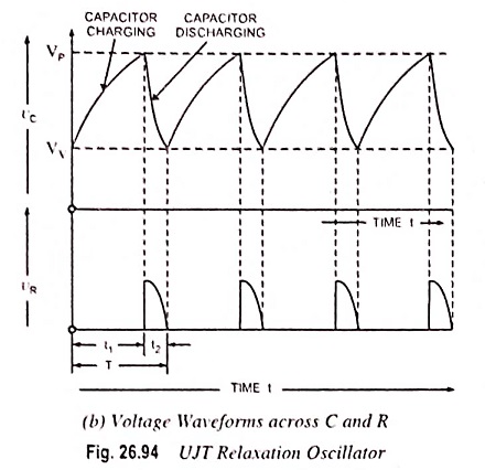
UJT Relaxation Oscillator – The relaxation oscillator shown in Fig. 26.94 (a) consists of UJT and a capacitor C which is charged through resistor RE when interbase voltage VBB is switched on. During the charging period, the voltage across the capacitor increases exponentially until it attains the peak point voltage VP. When the capacitor voltage attains voltage VP, the UJT switches on and the capacitor C rapidly discharges via B1. The resulting current through the external resistor R develops a voltage spike, as illustrated in Fig. 26.94 (b) and the capacitor voltage drops to the value VV. The device then cuts off and the capacitor commences charging again.
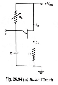
The cycle is repeated continually generating a sawtooth waveform across capacitor C. The resulting waveforms of capacitor voltage VC and the voltage across resistor R(VR) are shown in Fig. 26.94 (b). The frequency of the output sawtooth wave can be varied by varying the value of resistor RE as it controls the time constant (T = REC) of the capacitor charging circuit. The discharge time t2 is difficult to calculate because the UJT is in its negative resistance region and its resistance is continually changing. However, t2 is normally very much less than t1 and can be neglected for approximation.
For satisfactory operation of the above UJT Relaxation Oscillator, the following two conditions for the turn-on and turn-off of the UJT must be met, as derived in previous article (UJT Triggering of SCR Working Principle) (Eqs. (26.37) and (26.38)).
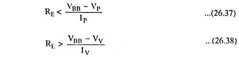

i.e., the range of resistor RE should be as given below

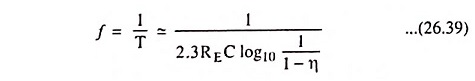
The time period and, therefore, frequency of oscillation can be derived as below.
During charging of capacitor, the voltage across the capacitor is given as
![]()
where REC is the time constant of the capacitor charging circuit and t is the time from the commencement of the charging.
The discharge of the capacitor commences at the end of charging period t1, when the voltage across the capacitor vC becomes equal to VP i.e., (η VBB + VB)
![]()
Neglecting VB in comparison to η VBB we have
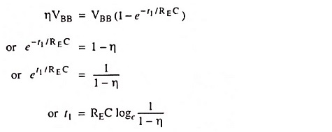
So charging time period,
![]()
Since discharging time duration t2 is negligibly small as compared to charging time duration t1, so taking time period of the wave, T = t1
Time period of the sawtooth wave,

and frequency of oscillation
By including a small resistor in each base circuit, three useful outputs (sawtooth waves, positive triggers, and negative triggers), as shown in Fig. 26.95, can be obtained.
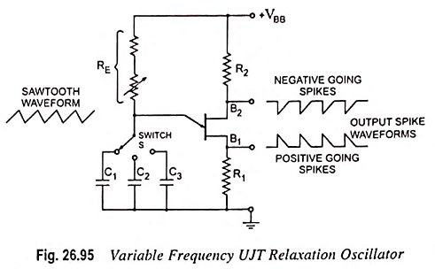
When the UJT fires, the sudden surge of current through B1 causes a voltage drop across R1 and produces the positive going spikes. Also, at the UJT firing time, the fall of VEB1 causes IB2 to rise rapidly and generate the negative going spikes across R2, as shown in Fig. 26.95. R1 and R2 should be much smaller than RBB to avoid altering the firing voltage of the UJT. A wide range of oscillation frequencies can be achieved by making RE adjustable and including a switch to select different values of capacitance, as illustrated.
As already mentioned in previous article (UJT Triggering of SCR Working Principle), there is upper and lower limits to the signal source resistance RE for the satisfactory operation of the UJT [refer to Eqs. (26.37) and (26.38)].