Push Pull Amplifier – Circuit Diagram and its Workings:
As we know already that, double-ended or push pull amplifiers makes use of two identical transistors in a single stage. It consists of two loops in which the transistor collector currents flow in opposite directions but add in the load. Push Pull Amplifiers eliminate all of the three drawbacks.
The push pull amplifier is a power amplifier and is frequently used in the output stages of electronic circuits. It is employed whenever high output at high efficiency is required. The audio power amplifiers used in transistor receivers, tape recorders, record-players, public address systems etc. make use of such circuits. These systems are usually operated by batteries or cells and, therefore, amplifier efficiency is of prime importance.
Basic Working Principle:
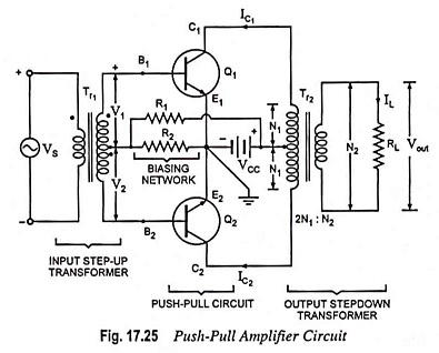
The basic principle on which a push pull amplifiers operates is that the input signal is converted before amplification, into two separate signals, which are identical except for a 180° phase difference. Each of these signals is applied as the input to one of the transistors of the push-pull amplifier. Since the inputs to the two transistors are 180° out of phase, so the output of the transistors.
The output transformer is connected in the collector circuits of the transistors in such a way that the collector currents of the two transistors combine to provide an overall signal having the same waveform as the original input signal. The magnitude of this combined output signal is larger than the input signal. push pull amplifiers can be operated in class A, class AB or class B mode.