Complementary Symmetry Push Pull Amplifier:
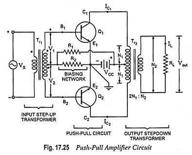
The use of transformers, at input as well as at output ends, in the push-pull amplifier shown in Fig. 17.25 makes it bulky and expensive especially in this age of the integrated circuits. Another drawback of the circuit given in Fig. 17.25 is that it needs two out-of-phase signals which necessitates an input tapped transformer or phase inverter, and thus makes the driver circuitry quite complicated. The above two drawbacks of an ordinary push-pull amplifier have been overcome in the complementary symmetry push pull amplifier.
Operations:
This complementary symmetry push pull amplifier arrangement uses two transistors having complementary symmetry (one N-P-N and another P-N-P). The term complementary arises from the fact that one transistor is the N-P-N type and the other is P-N-P type. They have symmetry as they are made with the same material and technology and are of same maximum rating.
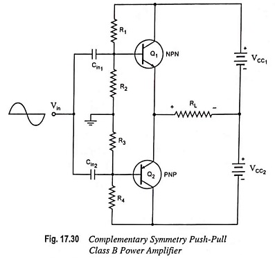
The circuit of a complementary push-pull class AB power amplifier is shown in Fig. 17.30. The resistors R1 and R2 provide the voltage divider bias to forward bias the emitter-base junction of transistor Q1 and similarly resistors R3 and R4 provide the voltage divider bias for emitter junction of transistor Q2. The resistors are so selected that under zero signal condition, the operating point is at cutoff and so no collector current flows.
The signal applied at the input goes to the base of both the transistors. The two transistors conduct in opposite half cycles of the input. For example during the positive half cycle of the input signal, the NPN transistor Q1 is forward biased and conducts while the PNP transistor Q2 is reverse biased and so does not conduct. This results in a half cycle of output voltage across the load, resistor RL. Similarly during the negative half cycle only the PNP transistor Q2 is forward biased and conducts and develops second half cycle of the output voltage across the load resistor RL. Transistor Q1 being reverse biased does not conduct during the negative half cycle of the input signal. Thus, during a complete cycle of input, a complete cycle of the output signal is developed.
Since collector current from each transistor flows through the load during alternate half cycles of the input signal, no centre tapped output transformer is required. However, for impedance matching an output transformer (without centre tapping) can be used.
Drawbacks:
One obvious drawback of this complementary symmetry push pull amplifier circuit arrangement is the requirement for two supply voltages. Another drawback of this circuit is difficulty of obtaining matched complementary transistors. If there is an unbalance in the characteristics of the two transistors, even harmonics will no longer be cancelled and considerable distortion will be introduced. Very often negative feedback is used in power amplifiers to reduce nonlinear distortion.