Up Down Circuit Analysis:
Any circuit has independent variables (such as source voltages and branch resistances) and dependent variables (such as voltage drop across resistors, current and power). Determination of response of dependent variables to variation in independent variable is known as circuit Up Down Circuit Analysis.

Consider a circuit given in Fig. 7.24. A voltage VS of 5 V is applied to a diode in series with a load resistance RL of 500 Ω. There are five dependent variables-voltage across load resistor, VL, load current I, power dissipation of diode, PD, power dissipation by load resistor, PL and total power PT.
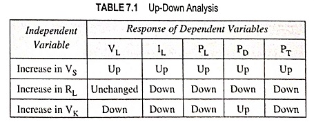
Now we are to determine how each of these dependent variables respond when supply voltage VS increases/decreases. The diode has a voltage drop of 0.7 V (equal to knee voltage). When the source voltage is increased, the voltage drop across the diode remains unchanged. Obviously voltage drop across load resistance RL will increase which will cause increase in load current IL. An increase in load current IL will make the diode power PD and load power PL to increase. The total power PT, being the sum of PD and PL will also increase.
When the load resistance RL is increased, the load voltage VL will remain unchanged owing to fixed voltage drop across diode (being equal to knee voltage VK or VD). Obviously, the load current IL will decrease. The decrease in load current means reduced PD, PL and PT.
If knee voltage increases slightly, the dependent variables VL, IL, PL and PT will decrease while PD will increase.
Table 7.1 summarizes the Up Down Circuit Analysis for increase in different independent variables.