Miller Sweep Circuit and Miller Bootstrap Sweep Circuit:
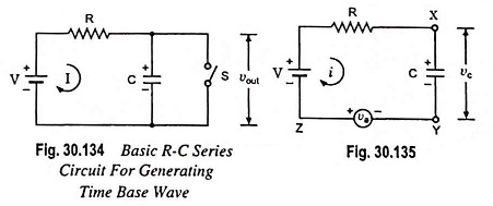
The basic R-C sweep circuit is shown in Fig. 30.134, in which opening of switch S provides sweep voltage, as already explained earlier. The waveform generated by this basic circuit is not exactly linear, even if the ratio of sweep voltage Vs and the supply voltage V is kept high. However, the linearity can be improved if feedback arrangement, such as Miller sweep and bootstrap circuits, is made with this basic circuit.
Feedback can be provided if an auxiliary variable voltage generator va is introduced in such a way that variable voltage va is always equal to voltage developed across capacitor C, as shown in Fig. 30.135.
Applying Kirchhoff’s voltage law to the circuit shown in Fig. 30.135,

i.e. the charging current i is independent of charging capacitor C and is constant.
Voltage across capacitor,
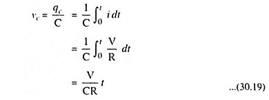
Hence, by introducing an auxiliary variable voltage generator in the basic R-C series circuit in the above manner, perfect linearity can be achieved in the output waveform of the circuit. This is the basic idea that is used in Miller sweep circuits.
Normally electronic circuits are assembled on a metallic chassis which is electrically connected to one point or node of the circuit. Then chassis and that point or node are referred as ground. In the circuit of Fig. 30.135 either point Y or Z may be grounded. The difference in selection of point to be grounded provides the difference in description of Miller sweep and Miller bootstrap circuit.
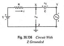
Suppose point Z of circuit shown in Fig. 30.135 is grounded and the circuit is redrawn as in Fig. 30.136.
Since vc = va, linear sweep will appear between Y and ground (or point Z) and will increase in the negative direction as seen by polarity of the auxiliary generator.
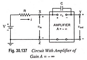
Now let us replace the auxiliary generator by an amplifier with YZ as output terminals and XZ as input terminals, as illustrated in Fig. 30.137.
Since the magnitude of the generator voltage va is always equal and opposite to that developed across the capacitor (i.e. vc) at every instant of time, the input vin to the amplifier is zero. In other words, points X and Z are at the same potential or point X also behaves as a virtual ground. Since voltage gain of an amplifier is given as A = vout/vin, for output vout to be finite gain A must be ideally infinite. Since the circuit shown in Fig. 30.137 resembles the circuit of an op-amp (operational amplifier) as an integrator, this circuit is called the Miller sweep circuit.
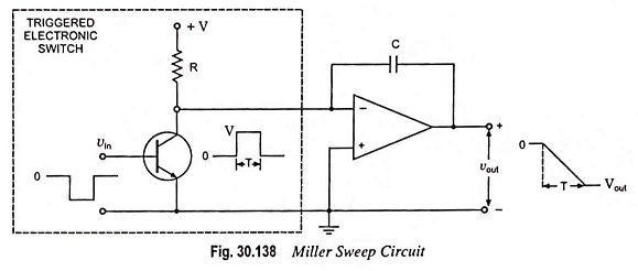
Miller sweep circuit shown in Fig. 30.138 is the basic schematic of a widely used sawtooth generator. The amplifier acts to increase the aiming potential; thus, linearity is improved and the output amplitude is increased. As the integral of a step function is a ramp, it is evident that this circuit would provide a sawtooth output.
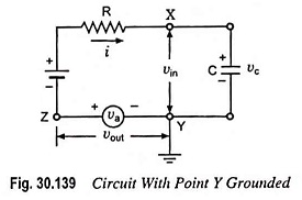
Now let point Y of circuit shown in Fig. 30.135 is grounded and the circuit is redrawn as in Fig. 30.139. For vc = va, a linear sweep will appear between point Z and ground (i.e. point Y).
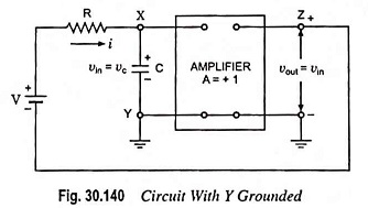
The auxiliary generator is now replaced by an amplifier with output terminals ZY and input terminals XY, as in Fig. 30.140.
Since input voltage to amplifier, vin = voltage developed across capacitor C, vc and output voltage vout = va = vc = vin, it implies that amplifier voltage gain A must be equal to unity. This circuit is referred to as a Miller bootstrap sweep circuit because in this circuit battery voltage V is lifted by its own bootstraps.
The characteristic of unity gain of amplifier can only be fulfilled by an emitter follower in transistor circuit.
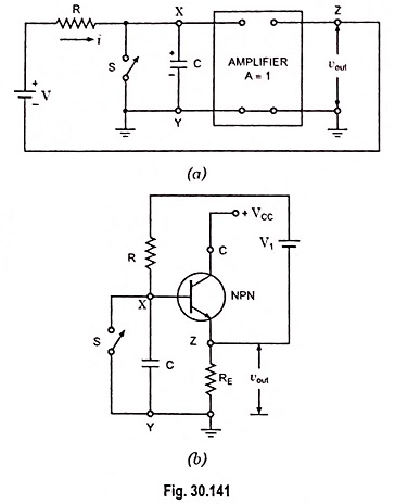
For comparison let us redraw the circuit of Fig. 30.140 in Figs. 30.141 (a) and (b). In Fig. 30.141 (b) an amplifier (with A ≡ 1) block is replaced by an emitter follower circuit.
Initially when switch S is closed, a current will flow from battery V1 in the loop formed by Z, V1, R, X, S, Y and RE. This causes a small voltage drop of v′ volts in the direction opposite to that of vout, as shown in Fig. 30.141 (b). The sum of V1 and v’ equals V in Fig. 30.141 (a).
The main drawback of this circuit is non-availability of perfect constant current through capacitor C which is due to the fact that neither terminal of battery V1 is directly grounded.
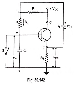
The above drawback, however, may be overcome by replacing battery V1 by a capacitor C1 as shown in Fig. 30.142.
The capacitor C1 is charged from VCC through R1, C1 and RE. The capacitor C1 is chosen of large value so that voltage across it shall not change appreciably during sweep time period. Since gain of an emitter follower is unity, its output voltage vout is equal to input voltage vin. Thus vA = vin = vout.
From the circuit shown in Fig. 30.142,
Voltage at point B,
![]()
Also

From equations (30.20) and (30.21) we have
![]()
Since vC1 does not change during sweep time period, the voltage drop iRR remains constant and, therefore, current iR through R is also constant. If the emitter follower circuit is designed to have high input impedance characteristic, current flowing through resistor R would pass through capacitor C. Thus current through capacitor C will be constant and voltage across it will be a ramp rising linearly with time with constant current iR.
Hence a sweep wave is produced using bootstrap principle.