Single Phase Full Wave Controlled Rectifier (or Converter):
In case of Single Phase Full Wave Controlled Rectifier (or Converter) both positive and negative halves of ac supply are used and, therefore, the effective value of dc voltage is high and ripple content is less compared to half-wave rectifiers. There are two basic configurations of Single Phase Full Wave Controlled Rectifier. Their classification is based on the type of configuration used i.e., mid-point converters and bridge converters. The diodes used in full-wave rectifiers, may be partially or completely replaced by thyristors.
Mid-Point Converters (M-2) Connection:
In a Single Phase Full Wave Controlled Rectifier circuit with midpoint configuration two thyristors and a single phase transformer with centre-tapped secondary windings are used. These converters are sometimes called the two pulse converters because two triggering pulses or two sets of triggering pulses are to be produced during every cycle of the supply to trigger the different thyristors. Such circuits are generally used for low rating outputs.
1. With Resistive Load: The circuit of a mid-point converter with resistive load is shown in Fig. 27.7. In this circuit, two thyristors are connected to the centre-tapped secondary of a transformer, as depicted in Fig. 27.7. The input signal is coupled through the transformer to the centre-tapped secondary. The circuit operation is explained below.
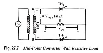
When terminal A shown in the circuit is positive w.r.t. midpoint N of the transformer secondary, point B will have negative polarity w.r.t. mid-point. Under this condition the thyristor TH1 conducts when it is fired at an angle α. The current through and voltage across the load are shown by the waveforms in Fig. 27.8. The current continues to flow up to angle π radians or 180° when the supply voltage reverses its polarity and thyristor TH1 gets turned off by natural commutation. During the negative half cycle of ac supply, the terminal B of the transformer secondary is positive w.r.t. to mid-point N. Thyristor TH2 gets turned on when it is gated. Usually the firing angles for the two thyristors are taken to be equal so as to avoid unequal distribution of load current in the two halves of input cycle.

Each half of the input wave is applied across the load. Thus, across the load, there are two pulses of current in the same direction. Hence the ripple frequency across the load is twice that of the input supply frequency. It is clear from Fig. 27.8 that with pure resistive load, the load current is always discontinuous.
The voltage and current relations are derived as follows.
The output dc voltage across the resistive load is given by
![]()
Average load current is given by
![]()
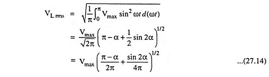
The expression for rms value of load voltage for a given firing angle α is
RMS value of load current is given by

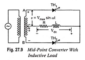
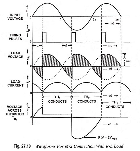
2. With Inductive Load: The effect of inductive load in case of mid-point converter is same as in case of half-wave converter, discussed earlier. The circuit of a mid-point converter using inductive load is shown in Fig. 27.9 and associated waveforms are shown in Fig. 27.10. In positive half cycle thyristor TH1 conducts when it is fired at an angle α. When ωt = π the cycle reverses and the voltage at terminal A goes negative while at terminal B it goes positive. At this value of angle thyristor TH1 still conducts due to current circulated as a result of decay of energy stored in the inductor. The rate of decay is determined by L/R ratio. When the energy stored in the inductor falls to zero, thyristor TH1 is turned off and the load current falls to zero value at an angle called extinction angle β. The extinction angle β may be greater than, equal to, or less than the firing angle α depending upon whether the value of inductance is more than, equal to or less than the critical value respectively. In case the extinction angle β is more than the firing angle α, the device is said to be in continuous conducting mode and when both angles α and β have the same value, the mode is called just continuous conduction mode. The waveforms depicted in Fig. 27.10 are for just conduction mode i.e. β = α. In case of discontinuous conduction mode extinction angle β has a value lesser than that of firing angle α.
The output dc voltage across the inductive load is given by

Some conclusions may be made from above equation:
- Output voltage will have the highest value for α = 0.
- Output voltage will be zero for α = 90°. It means that the output voltage will contain equal positive and negative areas, giving zero output voltage.
- For firing angle α exceeding 90°, the converter operates in inversion mode. The voltage will be negative maximum for α = 180°.
It is observed that the output power can be controlled to any value by varying the firing angle α between 0 and 90° in case of inductive loads, while in case of resistive load, the firing angle α ranges from 0° to 180°.
3. Effect of Freewheeling Diode: Circuit shown in Fig. 27.9 can be modified by using a freewheeling diode as depicted in Fig. 27.11. The operating principle of the rectifier is the same as that of without freewheeling diode except the fact that during the negative cycle, the load voltage becomes zero. The function of freewheeling diode is to divert the load current from the supply to the diode. The net result is that the magnitude of the net magnetizing current in the transformer secondary is reduced i.e., Idc sin Φ goes down.
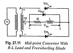
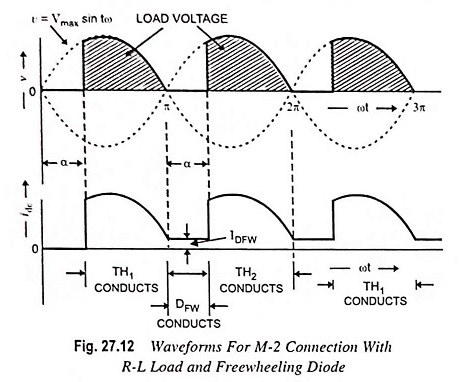
As Idc is the load current and remains constant, only sin Φ decreases. It means that angle Φ decreases which leads to an increase in power factor. Thus, the use of freewheeling diode improves the power factor of the load. The presence of freewheeling diode results in change in waveforms. As the supply voltage reverses, the load voltage is reduced to zero as it is shorted by the diode conducting the current circulated by the energy stored in the inductor. From the waveforms shown in Fig. 27.12, it can be observed that switching behavior of thyristor in case of R-L load is like that in a pure resistive load.
The average dc output voltage is given by

The dc load current is given by
![]()
It is also observed from Fig. 27.10, that the freewheeling diode DFW carries the load current during the firing angle α when the thyristors are not conducting. Hence the current through the freewheeling diode DFW is given by

Single-Phase Bridge Converter (B-2 Connection):
A single phase bridge converter needs 4 thyristors. This configuration leads to two quadrant operation. Such a converter is called the two-quadrant converter or fully controlled converter. Many times the bridge circuit is modified by replacing two thyristors by two diodes. This configuration leads to one quadrant operation (operation is restricted to first quadrant). Such a converter is called the one-quadrant converter or a semiconverter.
The load on the converter may be purely resistive, inductive (R-L) load or R-L-E load. An R-L-E load consists of resistance, inductance and motor (E stands for back emf of motor). The load may also have a battery (emf E) instead of motor.
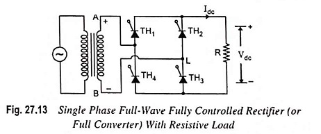
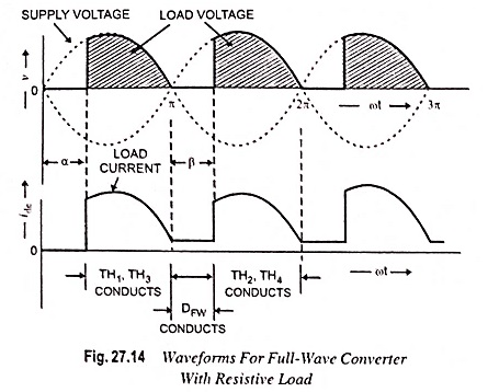
1. With Resistive Load: A fully controlled full-wave bridge rectifier is shown in Fig. 27.13. The operation of this circuit is in principle similar to that of the two pulse mid-point circuit shown in Fig. 27.7. All the four devices used in the circuit are thyristors TH1-TH4 for control of output power. In this circuit, diagonally opposite pair of thyristors are made to conduct, and are commutated, simultaneously. During the first positive half cycle, thyristors TH1 and TH3 are forward biased and if they are triggered simultaneously, the current flows through the load via thyristor TH1-load-TH3-source. Thus, during positive half cycle, thyristors TH1 and TH3 are conducting. During the negative half cycle of the ac input, thyristors TH2 and TH4 are forward biased and if they are triggered simultaneously, the current flows through the load via thyristor TH2-load-TH4-source. Thyristors TH1, TH3 and TH2, TH4 are triggered at the same firing angle α in each positive and negative half cycles of the supply voltage respectively. When the supply voltage falls to zero, the current also becomes zero. Thus thyristors TH1, TH3 in positive half cycle and TH2 and TH4 in negative half cycle turn off by natural commutation. The related voltage and current waveforms for this circuit are depicted in Fig. 27.14.
The relations for Vdc, Idc, VL rms and IL rms for this bridge configuration are similar to Eqs. (27.12), (27.13), (27.14) and (27.15), respectively.
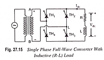
2. With Inductive Load: Figure 27.15 shows a single phase fully controlled bridge rectifier (or full converter) with R-L load. The fully controlled bridge rectifier provides two pulses in each cycle as in case of mid-point full-wave converter. The operating principle and waveforms of this circuit are similar to those obtained for mid-point full-wave converter. Firing angles for both the thyristor pairs are assumed to be equal. A large value of L will result in a continuous steady current in the load. A small value of L will produce a discontinuous load current for large firing angles. The waveforms with two different firing angles are depicted in Fig. 27.16.
The voltage waveform at the dc terminals comprises a steady dc component superimposed with an ac ripple component, having a fundamental frequency equal to twice that of ac supply.
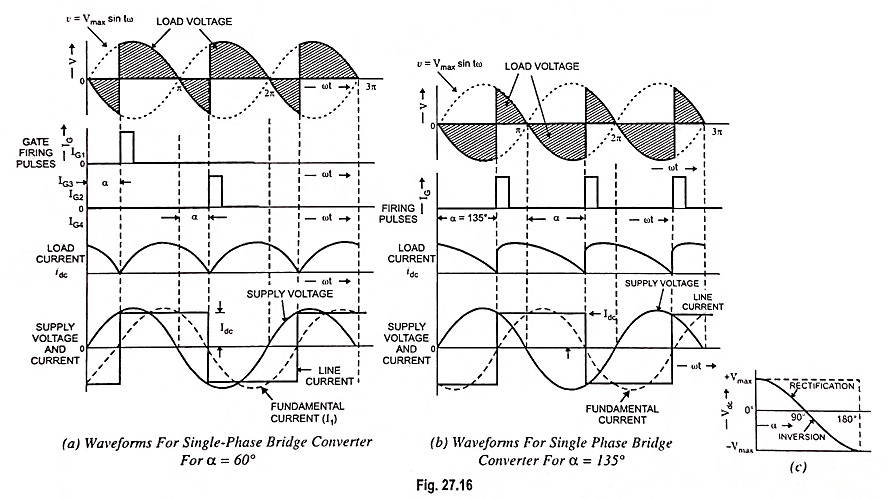
As illustrated in Fig. 27.16 (a), at firing angle α = 60°, thyristors TH1 and TH3 are triggered. Supply voltage from this instant appears across the output terminals and forces the current through the load. The load current Idc is assumed to be constant. This current also flows through the supply and the direction is from line to neutral, which is taken positive as depicted in Fig. 27.16 (a) along with the applied voltage. At instant π, the supply voltage reverses but because of very large inductance L, the current keeps flowing in the same direction at constant magnitude Idc. Thus the thyristors TH1 and TH3 remain in conducting state and therefore, the negative supply voltage appears across the output terminals. At an angle π + α, thyristors TH2 and TH4 are triggered. With this, negative supply voltage reverse biases thyristor TH1 through thyristor TH2 and thyristor TH3 through thyristor TH4 of commutating thyristor TH1 and TH3. The current continues flowing in every half cycle and output voltage is obtained as depicted in the figure. As illustrated the current is positive when TH1 and TH3 are conducting and negative when TH2 and TH4 are conducting.
The average output dc voltage is given by

The average value of output dc voltage can be varied, by varying firing angle α, continuously from positive maximum to negative maximum, assuming continuous current flow at the dc terminals. Because the average dc voltage is reversible even though the current flow in the load is unidirectional, the power flow in the convener can be in either direction. Thus full converter provides two modes of operation.
(a) Rectification Mode: For firing angle α less than 90°, the input ac supply is rectified by the circuit. The average value of voltage at the dc terminals is positive in the range from 0° to 90°, as illustrated in Fig. 27.16 (c) . In this mode, the power is transferred from the source to the load.
(b) Inversion Mode: For firing angle between 90° and 180°, the load voltage is negative which means that the power is supplied from the load to the source. Waveforms for α = 135° are shown in Fig. 27.16 (b) . Such an operation is used in the regenerative braking mode of dc drives and in high voltage direct current (HVDC) transmission.
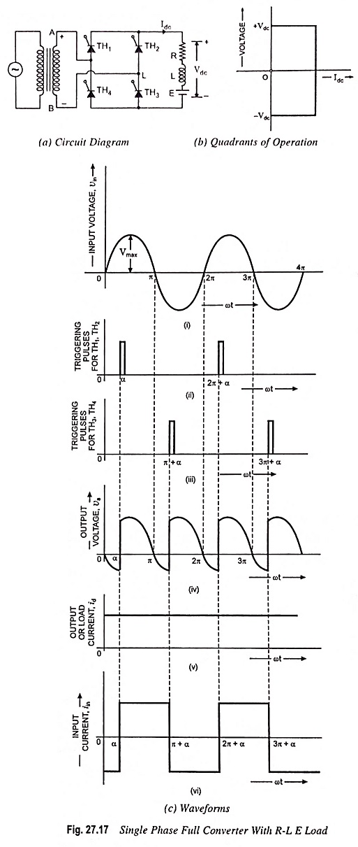
3. With R-L-E Load: The circuit arrangement of a Single Phase Full Wave Controlled Rectifier with R-L-E load is shown in Fig. 27.17 (a) . During positive half cycle, thyristors TH1 and TH3 are forward biased and start conducting at ωt = α. The load current flows through TH1, motor and TH3. At ωt = π, the supply voltages reverses. Because of inductance L thyristors TH1 and TH3 continue to conduct beyond ωt = π. From ωt = π to ωt = 2π, thyristors TH3 and TH4 are forward biased. When TH2 and TH4 are triggered at ωt = π + α, thyristors TH1 and TH3 are subjected to reverse bias and are turned off by natural commutation. Load current is transferred from TH1 and TH3 to TH2 and TH4. This mode of operation continues till TH1 and TH3 are triggered in the next positive half cycle. The quadrants of operation and waveshapes are shown in Figs. 27.17 (b) and 27.17 (c).
If the load is highly inductive, then time constant L/R is very high and the output current Idc remains constant.
The value of α should be such that when thyristors are triggered the instantaneous value of ac input voltage Vmax sin ωt is more than emf E. This sets a lower limit on firing angle α. The average output voltage of the converter is obtained from Eq. (27.20).
For continuous load current, we may write
![]()
During the period from α to π, the input voltage and input current are positive, and the power flows from the supply to the load. The converter is said to be operating in rectification mode. During the period from π to π + α, the input voltage is negative but the input current is positive and reverse power flows from the load to the supply. But the net power flow is from ac source to dc load because (π – α) > α [Fig. 27.17 (c)]
This converter is extensively used in industrial applications up to 15 kW.
Single Phase Half Controlled Bridge Rectifier or Semi converter:
When one pair of thyristors is replaced by diodes in a single phase fully controlled bridge circuit, the resultant circuit obtained is called the half-controlled bridge rectifier or semi converter. With this type of circuit, it is possible to provide a continuous control of the mean dc voltage, from maximum to virtually zero, but reversal of the mean output voltage is not possible. Thus, only a one-quadrant operation can be obtained from this circuit.
An R-L-E load supplied from single phase ac supply mains through a semi-controlled rectifier is shown in Fig. 27.18 (a). The circuit has two thyristors TH1 and TH2 and two diodes D1 and D2. The freewheeling diode DFW helps in conduction of current when thyristor is not conducting.
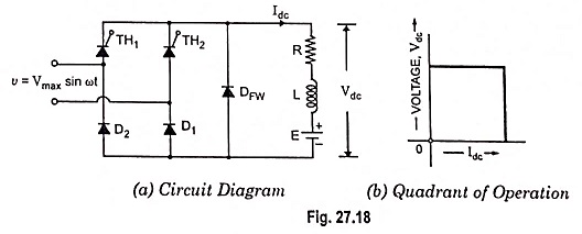
During positive half cycle thyristor TH1 is triggered at ωt = α and starts conducting. The value of α should be such that Vmax sin α > E. The current flows through TH1, motor and diode D1 from ωt = α to ωt = π. At ωt = π the input voltage becomes negative and freewheeling diode DFW is forward biased. Thus at ωt = π, thyristor TH1 and diode D1 stop conducting and current is transferred to DFW. During negative half cycle thyristor TH2 is forward biased and when it is triggered at ωt = π + α, the freewheeling diode DFW stops conducting and current is transferred to TH2, D2 combination. TH2 and D2 conduct from ωt = π + α to ωt = 2π. At ωt = 2π, thyristor TH2 and diode D2 get turned off and current freewheels through DFW from ωt = 2π to ωt = 2π + α. At ωt = 2π + α, thyristor TH1 is triggered again and next cycle of operation starts, Thus the circuit operation is: DFW conducts for 0 ≤ ωt ≤ α; TH1 and D1 conduct for α ≤ ωt ≤π; DFW conducts for π ≤ ωt ≤ π + α; and TH2 and D2 conduct for π + α ≤ ωt ≤ 2π.
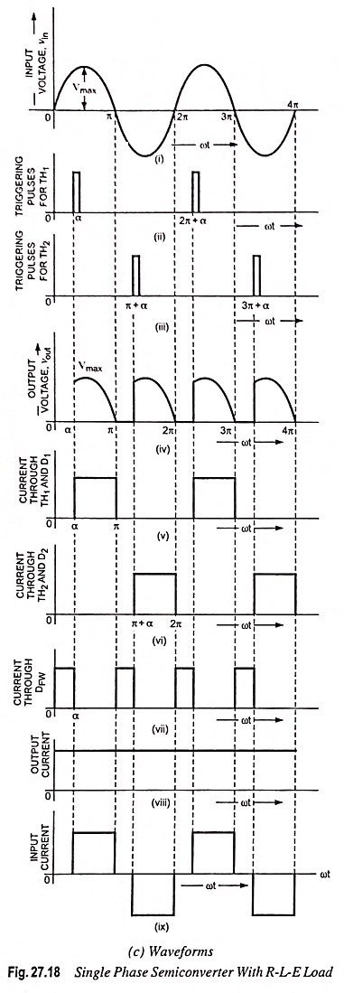
The quadrant of operation and waveshapes are shown in Figs. 27.18 (b) and 27.18 (c) respectively.
Average output voltage of semiconverter is given as

Average load current is given as

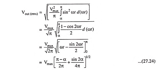
RMS value of load (or output) voltage of semiconverter is given as
RMS value of load current,

Output power,

Assuming output current lout to be ripple free RMS value of input current,
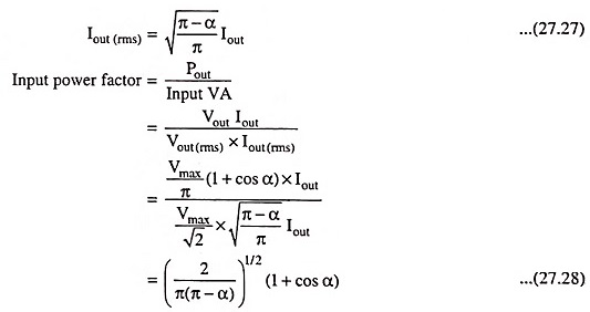
Phase controlled converters have poor power factor especially when the output voltage is less than the maximum, i.e., when tiring angle α is large. Semiconverters provide better power factor in comparison to full converters even though the improvement is marginal.
Advantages of Single-Phase Bridge Converter Over Single-Phase Mid-Point Converter:
- Thyristors are subjected to a PIV of Emax in fully controlled bridge converter and 2Emax in mid-point converter. Thus, for the same voltage and current ratings of thyristors, power handled by the bridge configuration is about twice of that handled by mid-point configuration.
- In mid-point configuration, each transformer secondary should be able to supply the total load. As such, transformer rating in mid-point configuration is double the load rating. This, however, is not the case in the bridge configuration.