Operation of Oscillator Circuit:
The use of positive feedback that results in a feedback amplifier having closed-loop gain |Af| exceeding unity and satisfies the phase conditions results in operation as an oscillator circuit. An Operation of Oscillator Circuit then provides a constantly varying output signal. If the output signal varies sinusoidally, the circuit is referred to as a sinusoidal oscillator and on the other hand if the output voltage rises quickly to one voltage level and later drops quickly to another voltage level, the circuit is usually referred to as a pulse or square-wave generator.
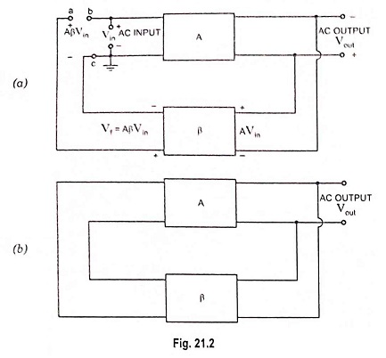
To understand how an Operation of Oscillator Circuit produces an output signal without an external input signal, let us consider the feedback circuit shown in Fig. 21.2 (a), where Vin is the voltage of ac input driving the input terminals bc of an amplifier having voltage gain A. The amplified output voltage is
![]()
This voltage drives a feedback circuit that is usually a resonant circuit, as we get maximum feedback at one frequency. The feedback voltage returning to point a is given by equation
![]()
where β is the gain of feedback network.
If the phase shift through the amplifier and feedback circuit is zero, then AβVin is in phase with the input signal Vin that drives the input terminals of the amplifier.
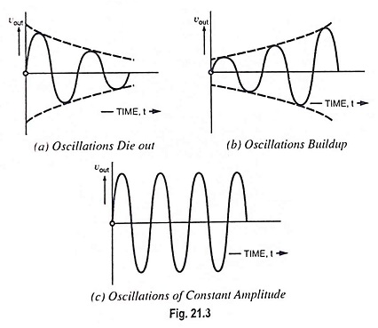
Now we connect point ‘a’ to point ‘b’ and simultaneously remove voltage source Vin, then feedback voltage AβVin drives the input terminals bc of the amplifier, as shown in Fig. 21.2 (b). In case Aβ is less than unity, AβVin is less than Vin and the output signal will die out, as illustrated in Fig. 21.3 (a). On the other hand if Aβ is greater than unity, the output signal will build up, as illustrated in Fig. 21.3 (b). If Aβ is equal to unity, AβVin equals Vin and the output signal is a steady sinewave, as illustrated in Fig. 21.3 (c). In this case the circuit supplies its own input signal and produces a sinusoidal output.
Certain conditions are required to be fulfilled for sustained oscillations and these conditions are that (i) the loop gain of the circuit must be equal to (or slightly greater than) unity and (ii) the phase shift around the circuit must be zero. These two conditions for sustained oscillations are called Barkhausen criteria.
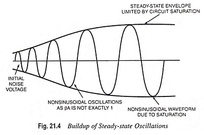
For initiation of oscillations, supply of an input signal is not essential. Only the condition βA = 1 must be satisfied for self-sustained oscillations to result. In practice βA is made slightly greater than unity, the system starts oscillating by amplifying noise voltage which is always present. Saturation factors in the practical circuits provide an average value of βA of 1. The resulting waveforms are never exactly sinusoidal. However, the closer the value of βA is to exactly 1, the more nearly sinusoidal is the waveform. Figure 21.4 shows how the noise voltage results in a buildup of a steady-state oscillation condition.
Another way of seeing how the feedback circuit provides Operation of Oscillator Circuit is obtained by noting the denominator in the basic feedback equation, Af = A/1+βA. When βA = – 1 or magnitude 1 at a phase angle of 180°, the denominator becomes zero and the gain with feedback, Af becomes infinite. Thus, an infinitesimal signal (noise voltage) can provide a measurable output voltage, and the circuit acts as an oscillator even without an input signal.
By deliberate design the phase shift around the loop is made 0° at the resonant frequency. Above and below the resonant frequency, the phase shift is different from 0°. Thus, oscillations are obtained at only one frequency, the resonant frequency of the feedback circuit.
To understand and apply the Barkhausen criterion, we must consider both the gain and phase shift of Aβ as a function of frequency. Reactive elements, capacitance in particular, contained in the amplifier and/or feedback causes the gain magnitude and phase shift to vary with the frequency.
In general, there will be only one frequency at which the gain magnitude is unity and at which, simultaneously, the total phase shift is equivalent to 0° (in phase—a multiple of 360°). The system will oscillate at the frequency that satisfies those conditions. Designing an oscillator amounts to selection of reactive components and their incorporation into circuit in such a way that the conditions will be satisfied at a desired frequency.
To show the dependence of the loop gain Aβ on frequency, we express Aβ(jω), a complex phasor that can be expressed in both polar and rectangular form :
![]()
where |Aβ| is the magnitude of the loop gain, a function of frequency, and θ is the phase shift, also a function of frequency. For satisfaction of Barkhausen criterion, we must have
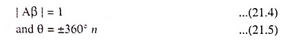
where n is any integer, including 0. In polar and rectangular forms, the Barkhausen criterion is expressed as
![]()