RC High Pass Circuit as Differentiator:
RC High Pass Circuit as Differentiator – A circuit that gives an output voltage proportional to the derivative of its input, is known as a Differentiator circuit.
![]()
Figure 29.1 shows a typical RC High Pass Circuit as Differentiator. The output voltage across R will be the derivative of the input voltage. It is important to note that merely an R-C series circuit will not provide the voltage across R as a derivative of the input. It is also necessary to set the proper circuit values.
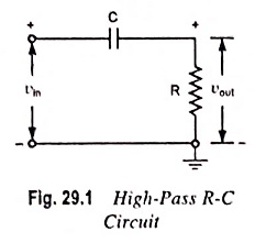
The conditions to be fulfilled are:
- The time constant RC of the circuit should be much smaller than the time period of the input signal i.e., RC << T.
- The value of Xc (i.e. 1/2πfC) should not be smaller than 10 times of R i.e., XC ≥ 10R.
When the given R-C circuit fulfills the above conditions then the voltage appearing across R will be derivative of the input. This is shown below.
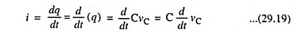
If vin be the input alternating voltage, i is the resulting alternating current then the instantaneous charge on the capacitor is given as
![]()
where vC is the instantaneous voltage across the capacitor C.
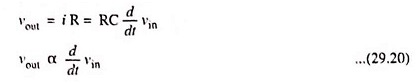
Current,
As the capacitive reactance is much larger than R(XC ≥ 10R), the voltage across the capacitor may be considered equal to the input voltage i.e., vC = vin
![]()
Output voltage,
Hence output voltage
![]()
If the input voltage is the square wave, output wave should be impulses of infinite amplitude and alternating polarity, occurring precisely at discontinuities of input. But in practice, the output impulses never exceed V maximum input amplitude, due to voltage drop across R, which is actually not negligible. Thus if the RC High Pass Circuit as Differentiator, input voltage Vin should appear across the capacitor C in totality at every instant. To realize this condition both R and C must be very small and XC >> R.
For the ramp vin = αt, the value of RC dv/dt is α RC except near the origin. The output approaches the proper derivative value only after a lapse of time corresponding to several time constants. The error near t = 0 is again due to the fact that in this region the voltage across resistor R is not negligible compared with that across capacitor C.
If it is assumed that the leading edge of a pulse can be approximated by a ramp, then the rate of rise of the pulse can be measured by using a differentiator. The peak output is measured on an oscilloscope, and from the equation vout = α RC, it is seen that this voltage divided by RC gives the slope α.
A criteria for good differentiation in terms of steady-state sinusoidal is that if a sine wave is applied to the circuit shown in Fig. 29.1, the output will be a sine wave shifted by a leading angle θ such that
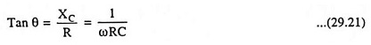
and the output will be proportional to sin (ωt + θ). In order to have true differentiation we must obtain cos ωt i.e. θ must be equal to 90°. This result can be had only if R = 0 or C = 0. However, if ωRC = 0.01, then 1/ωRC = 100 and θ = 89.4° which is sufficiently close to 90° for most purposes. If ωRC = 0.1, then θ = 84.3° and for some applications this may be close enough to 90°.
If the peak value of the input voltage is Vmax, the output is
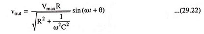
and if ωRC << 1, then the output is approximately Vmax ωRC cos ωt.
This result agrees with the expected value RC dvin/dt. If ωRC = 0.01, then the output amplitude is 0.01 times the input amplitude.