Constant Current Bias in Differential Amplifier:
In the differential amplifiers discussed so far, we have used the combination of RE and VEE to produce emitter dc bias current. Alternatively, constant current bias circuit can also be employed to set up the emitter dc bias current. Actually, the constant current bias in differential amplifier circuit is considered better as it provides current stabilization and, therefore, assures a stable operating point for the differential amplifier.
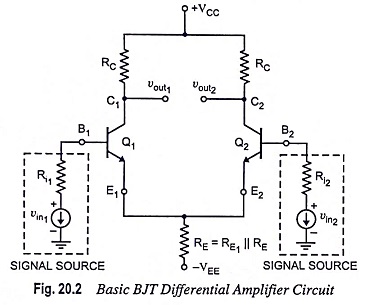
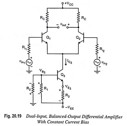
Dual-input, balanced-output differential amplifier with a resistive constant current bias is depicted in Fig. 20.19. By comparing the two circuits (circuits shown in Figs. 20.2 and 20.19) it is noticed that the emitter resistor RE has been replaced by a constant current transistor Q3 circuit. The dc collector current in transistor Q3 is established by resistors R1, R2 and R3 and may be determined as follows :
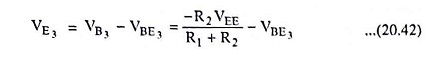
Voltage at the base of transistor Q3,
![]()
By voltage divider rule, neglecting base loading effect
Voltage at the emitter of transistor Q3,
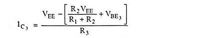
Collector current,
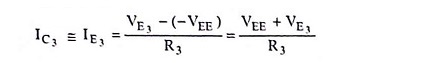
Substituting the value of VE3 from Eq. (20.42) in above equation, we have
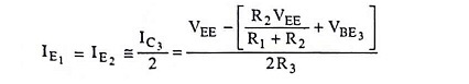
Because the two halves of the differential amplifier are symmetrical, each has half of the current IC3. Thus,
The collector current of transistor Q3(IC3) is fixed and must be invariant because there is no input signal into either the base or emitter of transistor Q3. Thus the transistor Q3 is a source of constant emitter current for transistors Q1 and Q2 of the differential amplifier [Fig. 20.19].
We have seen, in the analysis of differential amplifier circuits with emitter bias, that RE must be much larger than r′e i.e., RE >> r′e. The constant current bias, in addition to supply of constant emitter current, also provides a very high source resistance. This is because the ac equivalent of the dc current source is ideally an open circuit. Thus, all performance equations derived for the different configurations of differential amplifiers with emitter bias are also valid in case of differential amplifiers with constant current bias.
The thermal stability of the constant current transistor Q3 can be improved if resistor R1 is replaced by diodes D1 and D2 as depicted in Fig. 20.20. The base of transistor Q3 is biased with the voltage divider consisting of components resistor R2, and diodes D1 and D2. Diodes D1 and D2 assist in holding the emitter current IE3 constant even though there is large variation in temperature.
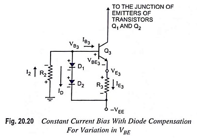
From the circuit shown in Fig. 20.20, it is seen that current I2 flows to the node at the base of transistor Q3 and then divides into diode current ID and base current IB3 of transistor Q3. In case the temperature of transistor Q3 goes up, its base-emitter voltage VBE3 reduces (in silicon transistors, VBE reduces by 2 mV/°C, and in germanium transistors, VBE reduces by 1.6 mV/°C). Because of reduction in VBE3, the voltage drop across R3 tends to rise and, therefore, emitter current IE3. On the other hand, the voltage drops across diodes D1 and D2 also reduce, causing a greater portion of current I2 to contribute to diode current ID. This causes the base current I3 to fall, which prevents any significant increase in emitter current IE3.
The transistor Q3 emitter current IE3 may be determined as follows :
Voltage at the base of transistor Q3,
![]()
Assuming equal voltage drop across the diodes and denoting it by VD, voltage at the emitter of transistor Q3,
![]()
and emitter current through transistor Q3,
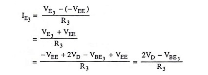
Assuming same characteristics for transistor Q3 and diodes D1 and D2 i.e., VD = VBE3, we have
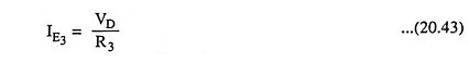
Thus the emitter current through transistor Q3 depends upon VD and resistor R3. The voltage drop across the diodes depends upon the diode current ID and diode current is a part of current I2 which depends upon the value of resistor R2. Thus emitter current IE3 can be varied by varying either R2 or R3.
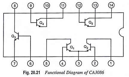
Performance can be made better, if we use a transistor array like CA3086 as a constant current source [Fig. 20.21]. Here an isolated transistor is employed, and required diodes are formed by employing transistors connected for diode operation. No doubt, discrete diodes will work as well. Figure 20.21 shows the functional diagram of CA3086.
For designing a constant current bias circuit depicted in Fig. 20.20, we may proceed as follows :
First of all let us choose a transistor Q3 emitter current I3.
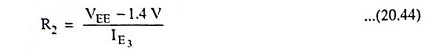
The values of resistor R3 and R2 now can be determined from Eqs. (20.43) and (20.44) respectively by assuming VD1 = VD2 = 0.7V and I2 = IE3
Often we use a zener diode in place of diodes as depicted in Fig. 20.22, because zeners are available over a wide range of voltages and can have a matching temperature coefficient of voltage to those of transistors.
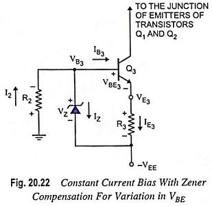
From circuit diagram given in Fig. 20.22.
![]()
and voltage at the emitter of transistor Q3,
![]()
and so the current through resistor R3,
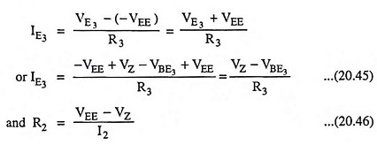
The value of R2 should be selected so as to provide I2 = 1.2 IZT where IZT is the minimum current required to cause the zener diode to conduct in the reverse region (i.e., to block the rated voltage VZ) and its value is specified on the data sheet of a zener diode.
The zener diode is quite useful for maintaining a constant base voltage and, therefore, the constant emitter current in a constant current bias circuit.