Constant Current Limiting Circuit:
A block of series regulation using simple Constant Current Limiting Circuit is shown in the Fig. 2.119. It is also called short circuit protection circuit as it provides protection against short circuiting. The resistance R4 is added in series with the pass transistor Q1 and the load which is called current sensing resistor.
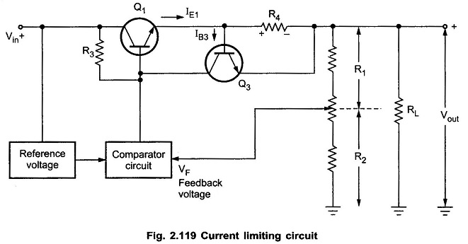
The drop across the current sensing resistance R4 is applied to the base-emitter of Q3. Under normal working condition and rated load current, this drop is insufficient to turn on the transistor Q3 and hence pass transistor Q1 continues to supply the rated load current.
When current increases due to over loading or short circuit conditions then drop across R4 increases more than 0.6 V. The 0.6 V is sufficient to turn on the transistor Q3. The collector current of Q3 flows through R3 and decreases the base voltage of Q1. This decreases the load voltage. This decrease in output voltage prevents the large load current.
The value of R4 can be selected to adjust the rated current of the circuit. As drop across R4 should be less than 0.6 V under normal working condition, for rated current of 1A, R4 can be selected as 0.7 Ω. For a rated current of 7A, R4 must be selected as 0.1 Ω and so on.
Let us study the variation of load current against load voltage with simple Current Limiting Circuit.
When RL = ∞ i.e. output terminals open, the output voltage is Vout = Vref .The load current is zero.
When load increases, the load resistance decreases and the load current increases. The load current can increase till the drop across R4 is not equal to 0.6 V. This load resistance at which drop across R4 is 0.6 V is say Rmin. When load current further increases and RL becomes zero (short circuit), the load voltage decreases and the load current gets maintained at a value less than current. After RL = Rmin, the regulation is lost and load voltage decrease as RL decrease. This is shown in the Fig. 2.120.
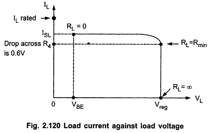
Let ISL = load current when load terminals shorted.
In such a case, drop across R4 is equal to VBE to turn on the transistor Q3.
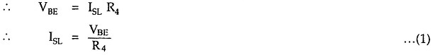
The minimum load resistance Rmin below which regulation is lost can be calculated as,

The practical value of Rmin will be slightly greater or less than this.
Disadvantage of Simple Current Limiting:
The disadvantage of constant current limiting is relatively large power dissipation in the series pass transistor when load terminals are shorted. Thus a large power rating transistor is required.
The power dissipation in the series pass transistor is given by,
![]()
where
- VBE = Base-emitter voltage of Q1
The circuit which is used in practice which eliminates the disadvantage of simple current limiting is called foldback Constant Current Limiting Circuit.
Such protection is provided in IC 723 with the help of resistance RSC connected to CL (current limiting) pin. The drop across RSC is applied across pins CL and CS. When this voltage becomes more than 0.6 V, it turns on internal current limiting transistor Q3 . The calculations of RSC for IC 723 are discussed earlier while discussing the applications of IC 723.