Dual Gate MOSFET – N Channel Depletion Type MOSFET:
Cross view of a dual-gate N-channel depletion type MOSFET is shown in Fig. 13.93. It acts as if two FETs are connected in series, as is obvious from Fig. 13.93.
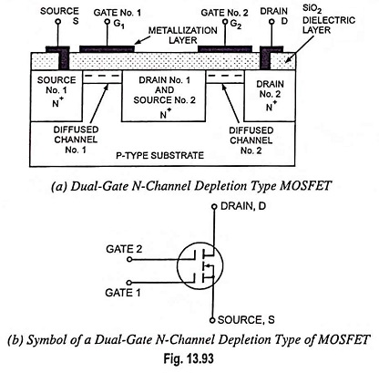
The middle block acts as drain for unit no. 1 and source for unit no. 2. Thus the current flow through the MOSFET is controlled by the voltage of both the gates. Drain current ID can be cutoff by making either gate sufficiently negative. The dual-gate MOSFET may be considered to be the counterpart of a tetrode (or pentode), due to the controlling capabilities exerted by two gates.
Although, Fig. 13.93 (a) may suggest a symmetrical device, it is Gate number 1 that provides the higher forward transconductance (gfs) of the two units (each gate has the same value of cutoff voltage, however). So, the signal under amplification is connected to Gate 1, while Gate 2 has the voltage that is to control the gain in an Automatic Gain Control (AGC) application.
Symbol indicating the substrate and case tied to the source is shown in Fig. 13.93 (b).