Gate Function in Network Function:
Gate Function in Network Function – By the use of step functions, any pulse of unit height can be realized. The pulse of width a can be generated by combining unit step function u(t) and delayed inverted unit step function by a time interval a as shown in Fig. 14.6.
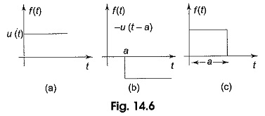
In Fig. 14.6(a), the unit step function u(t) combined with — u (t — a), the inverted unit step function, delayed by a results in the waveform shown in Fig. 14.6(c).
![]()
The gate function is only for 0 < t < a.
A periodic pulse train with pulse width a and pulse repetition period T1 may be generated by combining a sequence of positive unit step functions u(t), u (t — T1), u(t — 2T1)…, with negative unit step functions u(t — a), u(t — T1— a), u(t — 2T1— a)…, as shown in Fig. 14.7.
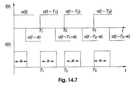
Therefore, the periodic pulses may be defined as,
![]()
Shifter Functions:
Consider unit functions such as unit step, ramp and impulse functions as discussed already. If these functions are displaced by ‘a’ second or delayed by `a’ second then these functions are said to be delayed functions. These are represented as shown in Fig. 14.5.
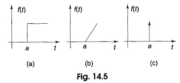
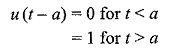
The delayed unit step function shown in Fig. 14.5(a) is defined as
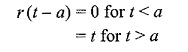
The delayed unit ramp function shown in Fig. 14.5(b) is defined as
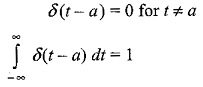
The delayed unit impulse function is defined as
Network Functions:
Network functions give the relation between the transform of the excitation to the transform of the response. Consider the network shown in Fig. 14.8.
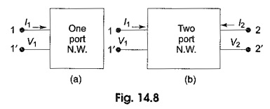
For the network shown in Fig. 14.8(a), only one voltage and one current exist and only one network function is defined. It constitutes of one pair of terminals called a port. Generally, a driving source is connected to the pair of terminals. For the two terminal pair network shown in Fig. 14.8(b), two currents and two voltages must exist, Normally in Fig. 14.8(b), 1-1′ and 2-2′ are called ports. Hence, it is called two-port network. If the driving source is connected across 1-1′, the load is connected across 2-2′. Otherwise, if the source is connected across 2-2′, the output is taken across 1-1′.